RC Speed Boat with PX4
Links to other episodes of the Boat series:
Properly integrating PX4 Autopilot
In my last post, I tested the basic functionality of the boat but didn’t actually use PX4 for its right purpose. So, in this post I will show how I integrated the Autopilot properly and made it actually control the boat.
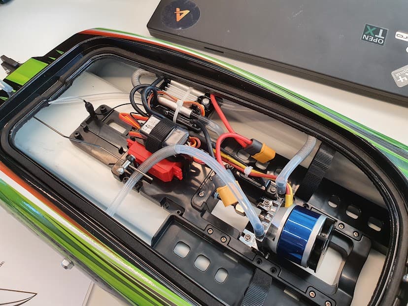
This is how the boat arrived out of the box. That looks quite empty ![]() , let’s fill it up with advanced sensors and autopilot components
, let’s fill it up with advanced sensors and autopilot components ![]()
What do we need?
So what’s missing from the last boat test? Remember, the goal is to make an autonomous boat. Let’s start with low-level concepts and list higher-level ones as we go on:
- Actuator output : Control authority of Thruster and Rudder from the PX4 Autopilot
- Rate control : Automatic attitude correction via rudder/throttle input
- Global position control : Automatic waypoint navigation/mission execution capability
And in this post we will tackle the first two (well, not much on the rate control but ![]() ) parts. Let’s get started!
) parts. Let’s get started!
Configuring Rudder/Thruster to be controlled by PX4
Using Dynamic Control Allocation
As PX4 is now moving onto the new Dynamic control allocation mixing system, I wanted to utilize this for the Boat project as well (also it’s way better than the legacy mixer system). In case you aren’t familiar, please check out this video

Fortunately, PX4 already had a matching geometry “Rover (Ackermann)” configuration. You can read more about the ackermann geometry here. Basically it’s a rover with a propulsion element & a steering control.
And since boats are technically equivalent to rovers driving on water surfaces, it is totally fine to use the rover configuration.
Creating a new RC boat airframe
In PX4, an ‘airframe’ is a file that contains all the custom configurations you need for a specific vehicle, and it gets loaded everytime you boot up the Autopilot.
And as I was planning to do a lot of development on the boat, I wanted a single airframe file that captures the history of changes I make. And also have a setting file that I can fall back to if I mess up the system so badly: if I need to do a whole parameter reset for example. Here’s the airframe I created:
The airframe file basically does the following:
- Loads the rover startup script that configures the vehicle as a basic rover :
rc.rover_defaults - Enables the dynamic control allocation
- Sets the control allocation geometry as the ‘Ackermann Rover’
- Sets the disarmed value for the Steering servo channel to be in centered position
- Enable the commander prearm mode so that Servos can move even if the vehicle is disarmed
After flashing the autopilot with the new firmware with this airframe file, you can enable the airframe by going to the Parameters tab and setting SYS_AUTOSTART to 50005, which is the ID I gave with the airframe filename 50005_bigstorm_catamaran.
You can read more about the system startup process of PX4 and airframe format in the user documentation.
Now we have the fundamentals set, let’s get onto actuator configuration ![]()
Actuator Mapping
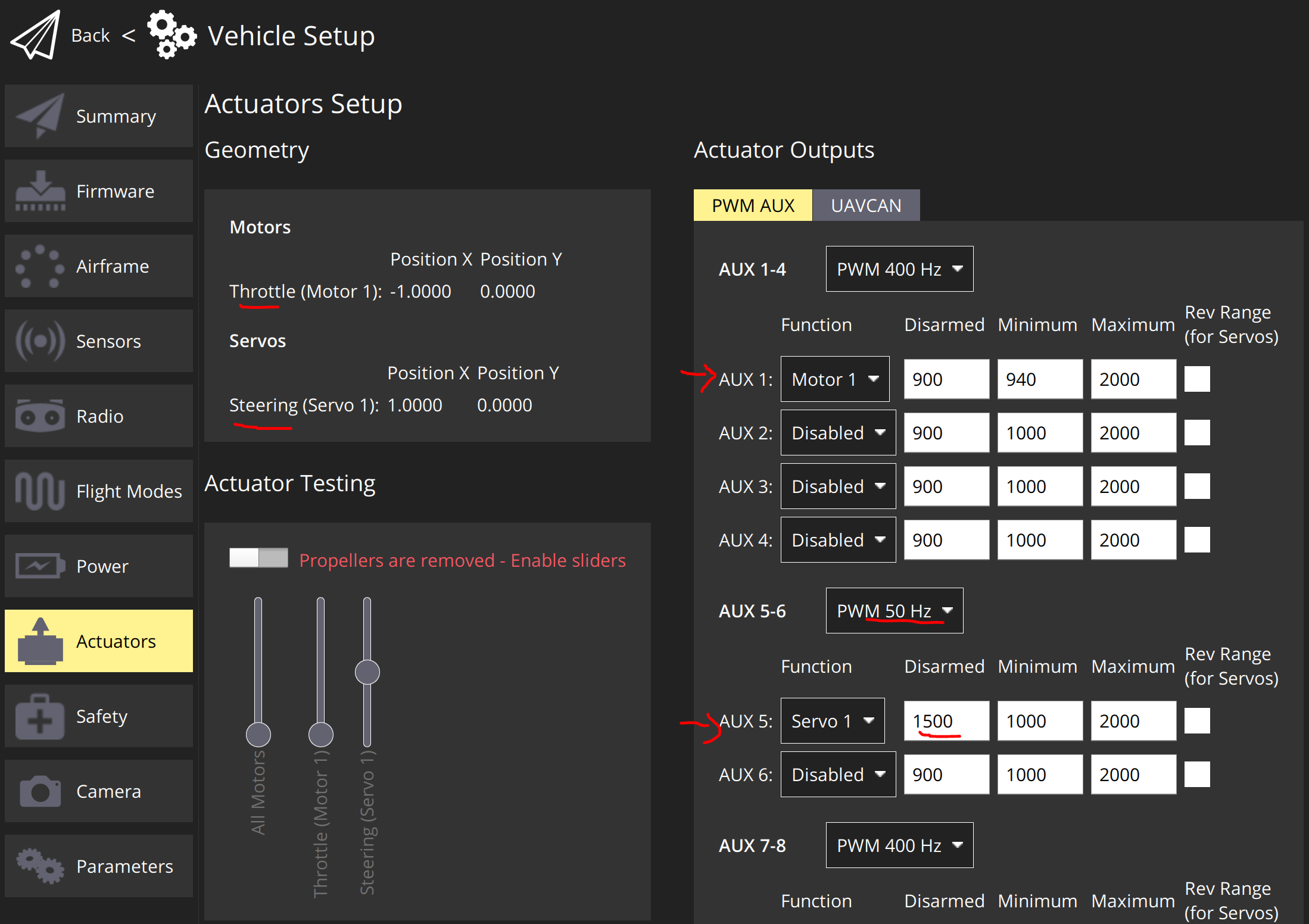
To map the correct outputs I want to use: FMU1 (AUX1) as Thruster and FMU5 (AUX5) as Steering, I had to configure in the Actuators tab few settings.
- Set the AUX 5-6 pinout group to PWM 50Hz protocol since Steering servo can only take 50Hz PWM output
- Set the AUX1 Function to
Motor 1and AUX5 toServo 1
That’s pretty much it. Once I did this and connected the signal cables to Pixhawk 4 mini, I could easily test the actuator output using the sliders, which is so helpful when developing an untested vehicle like the boat.
Other setups
RC receiver
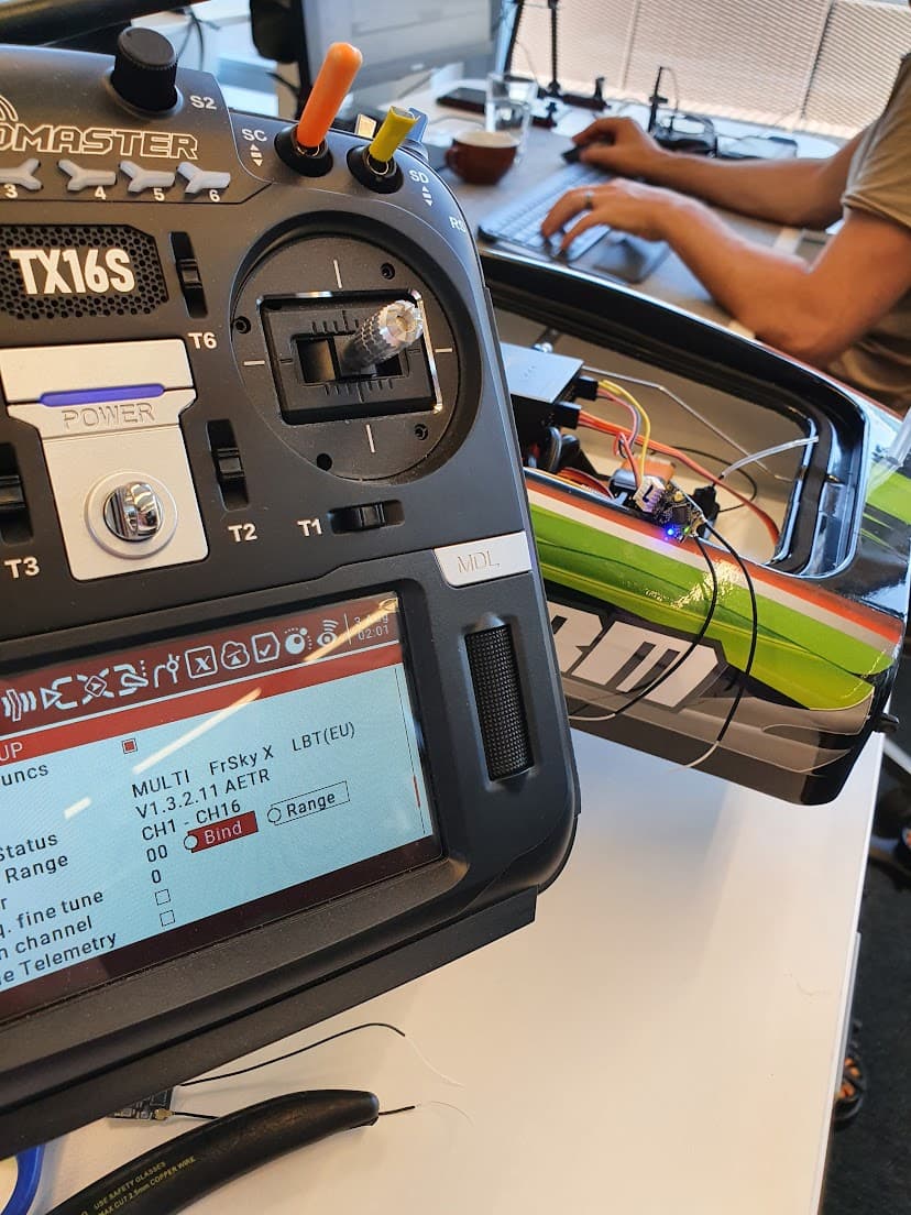
As I couldn’t use the simple 2 channel receiver due to it being old configuration of outputting 2 separate PWM output channels for throttle and yaw control, I decided to use a conventional transmitter/receiver.
I chose Radiomaster TX16S, which is running OpenTX program that allows you to flexibly connect to any type of receiver (and it’s open source). And the receiver that outputs the SBUS, which came with the transmitter.
Binding is hard!
As usual, there was an unexpected setback in most unexpected stages of the project. I just couldn’t bind my receiver with the transmitter! For some reason, it seemed to work but it wasn’t, but that wasn’t all.
The Pixhawk 4 mini takes the ‘PPM’ input using its Servo cable format IO interface, which is really convenient to use as most receivers come with the Servo style output (Signal / Power / Ground). So I tried several receivers but they just didn’t work, and when I clicked “calibrate” in QGC > Radio Setup screen, it would say: “Turn on the transmitter”, which meant that the receiver data wasn’t getting recognized properly.
And after a while, I realized that the receivers I am using is outputting in SBUS format, and not PPM (older format). This meant that:
- I couldn’t use the PPM RC input interface
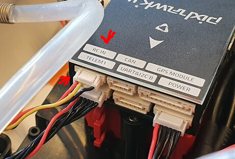
- I had to use the RC IN / SBUS input connector as the receiver output
Fair enough, I plugged in the receiver that already had the connecter soldered on that I used in my previous tests straight out of Pixhawk 4 and into Pixhawk 4 mini, and it didn’t work ![]() .
.
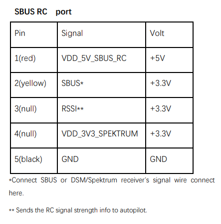
I was quite puzzled but after noticing that receiver wasn’t even on, I read the Pixhawk4 pinout document, and realized that the connected lines to the receiver were all totally wrong! The voltage/ground was swapped, and the SBUS signal line was connected to VDD_3V3_SPEKTRUM, which doesn’t really make sense.
So I swapped the pins in the connector and voila, the receiver was powered on and started outputting data after I binded the transmitter ![]()
Telemetry radio
If there’s one biggest lesson @sfuhrer taught me, that would be to “Always have a second connection”. You will read later on in this post but this saved me later during the test.
Anyways, to have a connection with the QGC (Ground station) during operation (which is really helpful), I added the Telemetry Radio, which was as easy as just plugging in the radio module to the TELEM1 port.
Cherry picking Rover Acro Control PR
Since @Jaeyoung-Lim has already started the PR that brings in acro mode support for Rovers, I wanted to test this out.
So I basically fetched this branch and cherry-picked it on top of the test branch I was using (which branched out of the main branch of PX4-Autopilot).
I then added some refactor commits to clean up the Rover Position Control module, which wasn’t really necessary (and is definetely not encouraged for creating PRs, as it doens’t bring in any functional changes and is more of a noise to the PR reviewers).
But I just can’t resist cleaning up the code when it’s so dirty (in my standards ![]() ). I will need to learn how to resist this temptation!
). I will need to learn how to resist this temptation!
More details
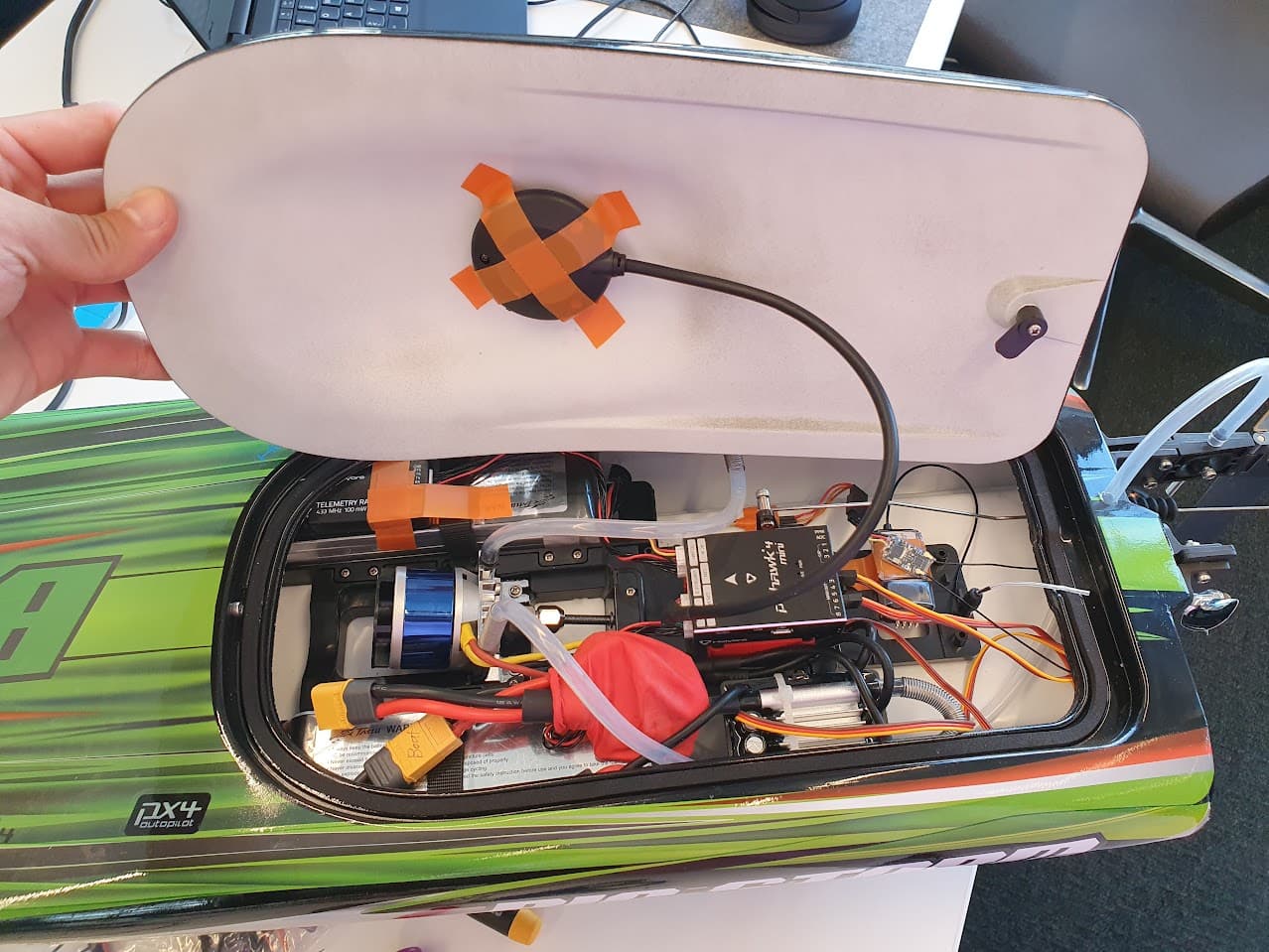
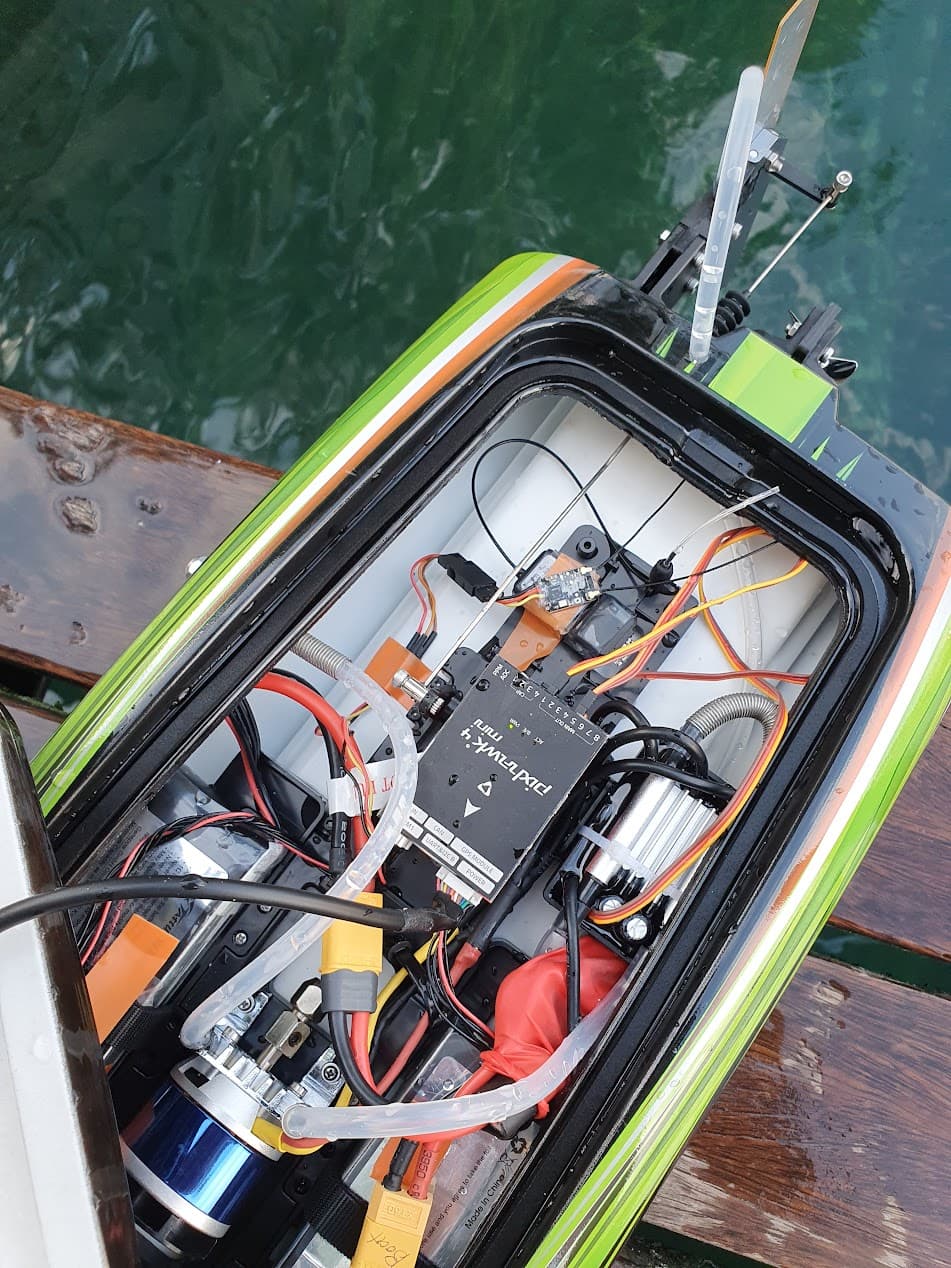
- I added batteries to both left and right side to balance out the boat (which hopefully would remove the inconsistent turn characteristics between left / right turns)
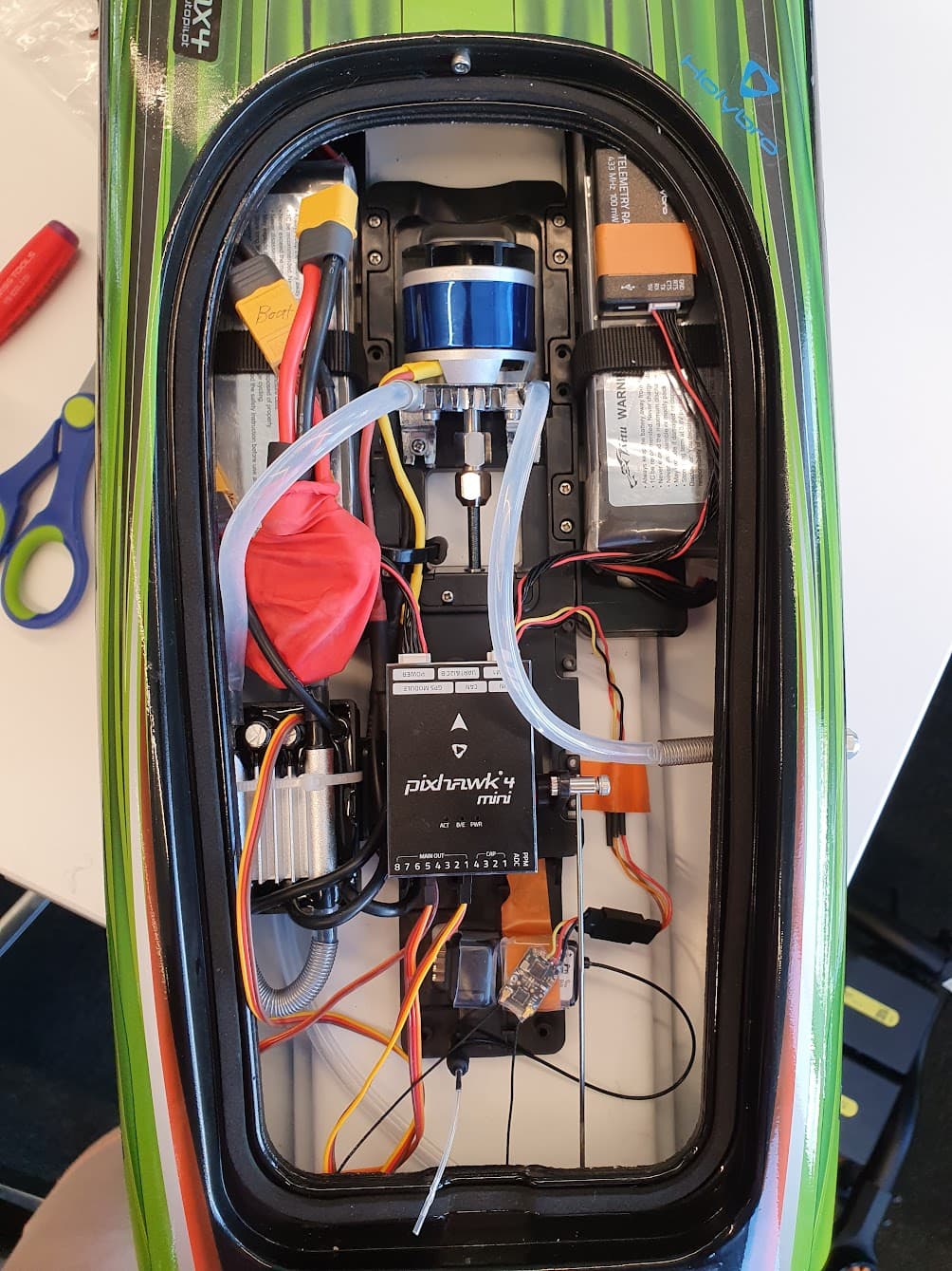
This is what the boat looked like after setting everything up.
This was a shot
Testing
Bench testing
First I checked if enabling the Acro mode has reasonable rudder movements when I move the boat around. It definitely had some jittery movements (which I need to check the log to exactly understand why), but it seemd all right (when I yaw it to right, rudder moves left which will try to yaw the boat back to left direction).
River bench testing : Failsafe
Before actually launching the boat to the water, I checked the “RC Lost Failsafe” behavior. Since you don’t want the boat to run away / do crazy stuff when you lose the RC signal ![]() .
.
I definitely encourage everyone to make sure you know exactly what’s going to happen when you loose the control by testing them. Please configure your failsafe correctly!! ![]()
When I first turned off the transmitter while the thruster throttle was at minimum, it actually went to higher throttle and started to do werid stuff. This puzzled me so I checked the failsafe action and it was set to “Return”. Which meant that boat tried to return to the launch spot, but of course this wasn’t desirable for me at this point since the dock has walls and obstacles all around, so the autonomous return feature would:
- Probably crash the boat to the wall (due to GPS inaccuracy)
- Probably do weird stuff (since Rover’s position control isn’t so smooth for now, as I haven’t tuned the vehicle and the rover guidance logic itself is probably not mature enough)
So I set it to “Lockdown”, (after reading the comments and code of PX4-Autopilot, I learned that it locks-down the actuators to their disarmed values, and is different from “flight termination”, but I still find their distinction confusing ![]() ) and expected the motors to stop completely.
) and expected the motors to stop completely.
Guess what happend when I disconnected the RC? It kept spinning more for 15 seconds, then stopped. Which left me even more puzzled. Why did it just do that? I don’t want the boat to be moving around for 15 seconds after RC signal is lost!

After some debugging session and reading through the code, I realized that there’s another paramter COM_RCL_ACT_T that defines the buffer time between RC signal loss and Failsafe action trigger ![]() . So setting that to 2 seconds did the trick of shutting down the motor within the reasonable time.
. So setting that to 2 seconds did the trick of shutting down the motor within the reasonable time.
And of course, I submitted the Issue ![]()
https://github.com/PX4/PX4-Autopilot/issues/19952
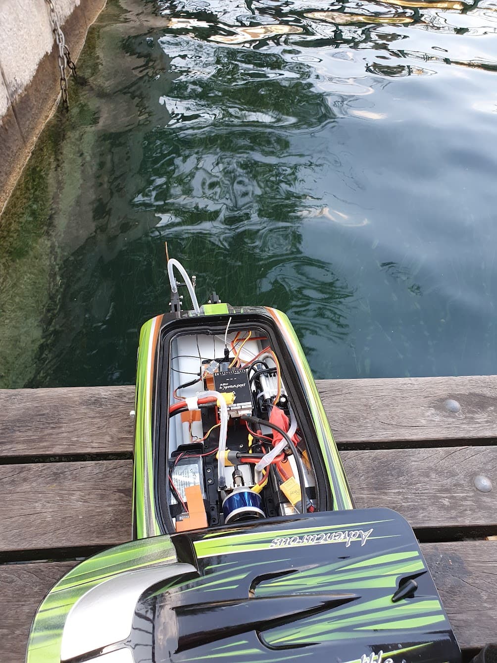
Water Testing
Now let’s get to the fun part. After verifying the failsafe behavior, I put the boat in the river and let it cruise using manual control.

After doing a couple of laps around, I started to increase the speed and did more aggressive turns. Which was super fun and I just wanted to get familiar with the controls using the RC transmitter, and it was super fun!
There were a couple of things I observed:
- Boat jumps up and down a lot (nose pitches up), and I supected this is because there’s not enough nose weight
- Boat accelerates really quickly once it reaches a certain speed / condition and it then kind of glides over the surface really fast. The speed increase curve felt exponential.
- Giving the full throttle doens’t necessarily lead to highest acceleration in the beginning phase when the velocity is low. This can be either limitation in the ESC, or more on the hydrodynamics (when your speed is low, the momentum applied by the thruster is limited by a factor of the speed)
Boat failing prearm checks
While testing, some errors started popping up on QGC like “Preflight check failed, GPS Speed Accuracy too low” from certain point. And the problem was that I couldn’t arm anymore using the RC controller.
This is where Silvan’s advice saved my day: “Always have the Telemetry Radio connection”. Had I not installed the radio, I probably wouldn’t have been able to regain control easily (and also wouldn’t have a clue what’s wrong with the vehicle).
So how do I fix this? Well it basically depends on the GPS sensor, and if the GPS output doesn’t improve, I will never be able to arm the vehicle.
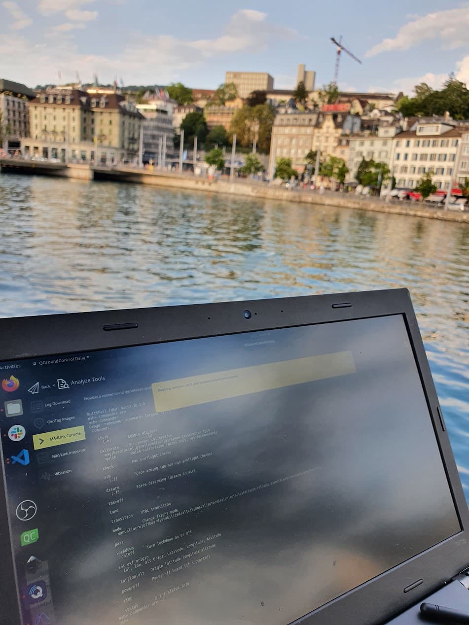
So I actually went to MAVLink console and did commander arm -f, which basically bypasses the prearm checks and directly arms the vehicle. This is definitely not an encouraged method to arm your vehicle, but for my case it was necessary as I at least needed to regain the control.
But then some more errors popped up like “Compass#0 fault!” which eventually disarmed the vehicle if I recall correctly. I had no idea why this was happening and tried to solve it by setting the MAG0 and MAG1’s priority to ‘Disabled’ (which would hopefully disable the usage of the magnetometers entirely), but I think the errors were still coming up. It was quite hectic haha.
Accidentally flipping the boat
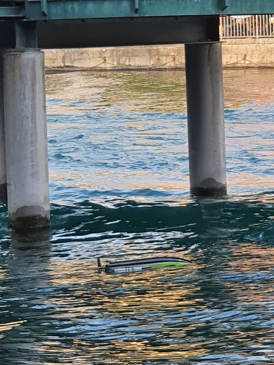
I then cruised around more, but of course no fun comes without accidents ![]() , while trying some more aggressive turns and high-speed maneuvers, I actually flipped the boat which was captured in the video below:
, while trying some more aggressive turns and high-speed maneuvers, I actually flipped the boat which was captured in the video below:

It was quite sad to watch the boat flipped upside down, unable to flip itself back up. I really wished that the boat-flip feature Mathieu discussed was a real thing when it happened.
What’s interesting to note was that the ‘emergency rudder’ that was supposed to safely guide the boat (according to the product manual) even when it’s flipped was useless as the thruster out of the water. Bad product marketing ![]() !
!
So the only solution was to swim to get the boat, and after getting it back, I realized that the thruster was not working and it had some water inside. But in the end, I was glad the boat was back.
Conclusion
Log Analysis
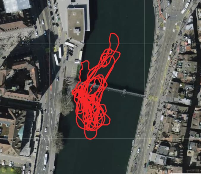
Here’s the log of the whole test. Please feel free to check it out and learn from the logs yourself!
Here’s what I noticed from the log:

First, I noticed a strong 2.5 ~ 3 Hz vibration, which seems to be related to the bouncy motion boat was having due to the pitch up / down behavior.
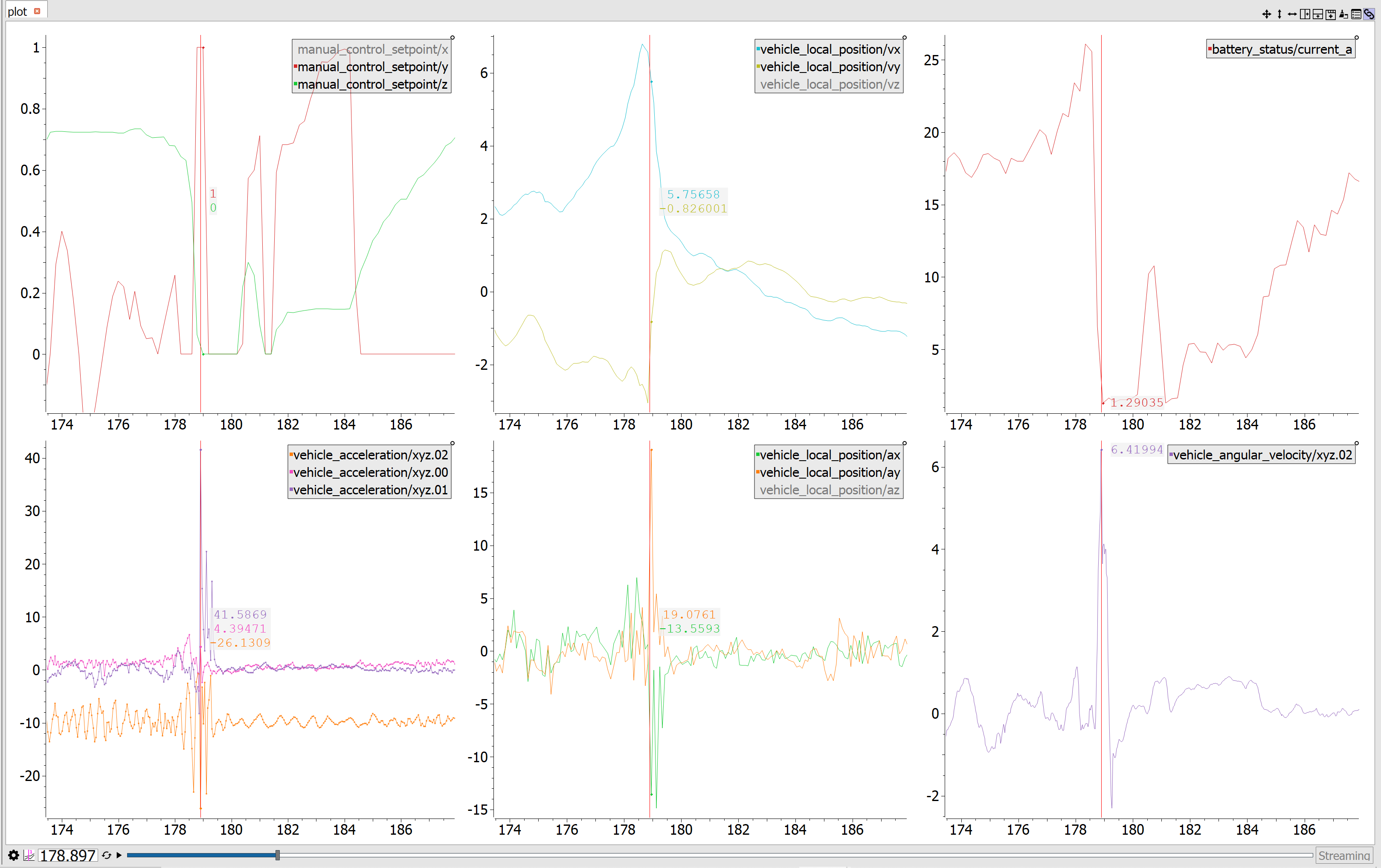
Second, I noticed that when I apply full rudder deflection (manual_control_setpoint/y, since PX4 uses Front-Right-Down axis convention and roll input from the RC controller is translated into the Y axis, which is in the Right direction), the boat reached 41 m/s^2 acceleration & 6.5 rad/s yaw rate, at the speed of around 6 m/s.
The math checks out (Radial acceleration = Angular rate * Tangential velocity), and it was fascinating to learn that the boat was experiencing 4G sideways acceleration! Also, the turn radius must have been around 1 meter (Velocity / Yaw rate), which is quite crazy to think about since the vehicle going at 6m/s is turning within 1 meter-ish distance and coming to a full stop.
Things that are still ambiguous to me
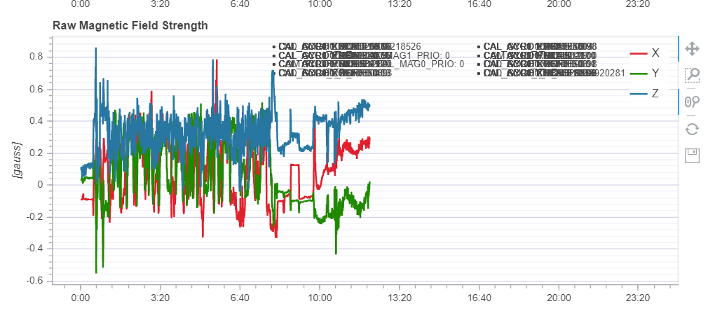
Here it’s visible when I disabled two magnetometers as it was causing the fault error (which also doesn’t allow you to arm the vehicle). But I am still not sure how this fault even occured.
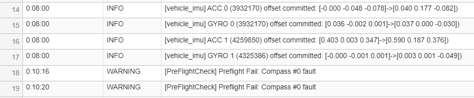
I noticed that the IMU sensors get new offsets committed during operation, and I don’t know why.
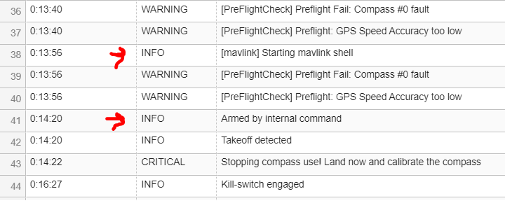
Here it is visible when I force-armed the vehicle. I am still unsure how the low GPS speed accuracy occurred ![]()
Thoughts
It was great to actually let the PX4 control the vehicle, and this is a big step up from the previous test where PX4 was merely a data logger.
But of course, there’s much more to do. Here are the next steps I am thinking of:
- Test the acro mode properly (change PID settings and check boat behavior) at a calm lakeside place
- Test the position control mode
- Test the mission mode, and do waypoint missions
Hope to meet you all in the next post! And this one got super long, so I will try to keep it short on the next one ![]()