RC Speed Boat with PX4
Motivation
PX4 is super cool, it can fly all the different flying vehicles in this world. But believe it or not, it can’t really drive rovers or boats that well.
I have heard so much about the Ardu-Rovers, and apparently, it’s really good. Why can’t PX4 be good at ground/water vehicles as well? I wanted to improve that!

rctestflight’s autonomous boat videos were a huge motivation for me in getting started with this project. Boats are just so fun! ![]()
![]() So this project’s aim is the following:
So this project’s aim is the following:
- Make the boat configuration/usage easy and intuitive (by modifying PX4-Autopilot flight control software and User guide documentation)
- Improve the autonomous control of the PX4 boat to a level that allows similar guidance/mission planning capability as multicopters
Also I wanted to document the journey as I go along, cause why not ![]()
The Boat (Amewi Big Storm racing boat catamaran)
![]() To do that, I purchased with the help of Auterion, an RC Speed boat that can go up to 60 km/h!
To do that, I purchased with the help of Auterion, an RC Speed boat that can go up to 60 km/h!

You can check out the boat in this shop link. The specs are more well defined in this conrad website.
The specific spec is the following:
- 2815 Brushless outrunner motor, water-cooled
- 37 gram Steering servo
- 60A Water cooled ESC (upto 4S voltage)
- Recommended battery : 2 x 2S LiPo 7.4V 3000 - 4000mAh 40C
- Body : ABS Plastic
- Drive shaft : 4mm flexible shaft
- Length : 740 mm
- Width : 180 mm
- Weight : 1200 g
First, tidying up the boat
This product is Almost-Ready-to-Run, so it has pretty much everything except the Battery. However, I had to go through some additional steps to get it working to the state that I wanted to.
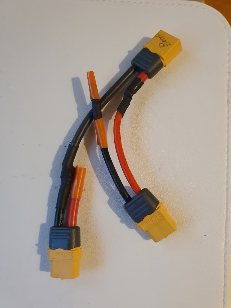
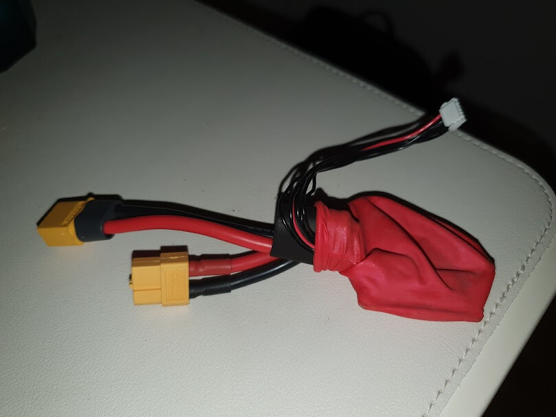
Creating a two XT60 connecter joiner
Remember how the recommended setup of batteries is having two 2-cell batteries on left/right side of the boat? Therefore the ESC has two XT60 connecters in series connection so that you can directly plug in two batteries.
However, I did not have a XT60 compatible 2-cell batteries at hand, which meant that I needed to basically re-join those split-out connectors and have a single XT60 connector, to which I would connect a 4-cell battery.
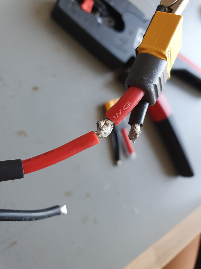
It was a tedious process and quite dumb (since I am re-joining the purposely split-out connectors ![]() ), but in the end a flux and a high-heat capacity soldering iron helped in making the connector
), but in the end a flux and a high-heat capacity soldering iron helped in making the connector ![]() .
.
Attaching a power module to measure battery voltage / amperage in real-time
Since I want the autopilot to have knowledge of battery voltage and amperage usage, I needed to connect a power module. An ideal unit to use would be something that has a XT60 connector on each side with a heat-shrinked (electrically isolated & water-resistant) power module, something like this:
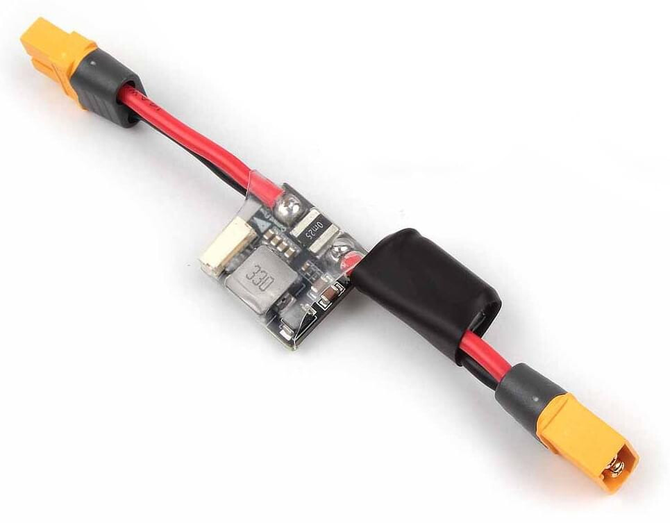
Image Source: Holybro PM02 power module
But of course, in real life you never have perfect conditions, and I couldn’t find a power module with that shape with a compatible connector (to connect according to the pixhawk 4 hardware specification) attached.
So I ended up using the Holybo Micro Power Module PM06, which meant that I am wasting 3 other connections (as you can connect up to 4 power outputs), but that was best I could do ![]() .
.

And since having exposed electrical pads like that in a crammed-space like inside the RC boat is an electrical short waiting to happen, I surrounded the power module with a rubber balloon to electrically isolate the board and make it water-resistant ![]()
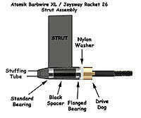
Applying the marine grease to the flexible shaft
Surprisingly, according to the RC community, is really important to apply the marine grease to the shaft that drives the rotor regularly (after a day of use even!).
So before running the rotor under high load, I got an RC Marine Grease gun kit and disassembled the shaft-motor coupler and pulled out the shaft to grease them properly ![]()
With a 7 or 8 mm Hex wrench, you can disassemble the coupler from this:
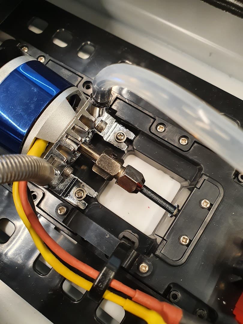
To like this:
And when you apply the grease, it has this blue-ish color which looks something like this:
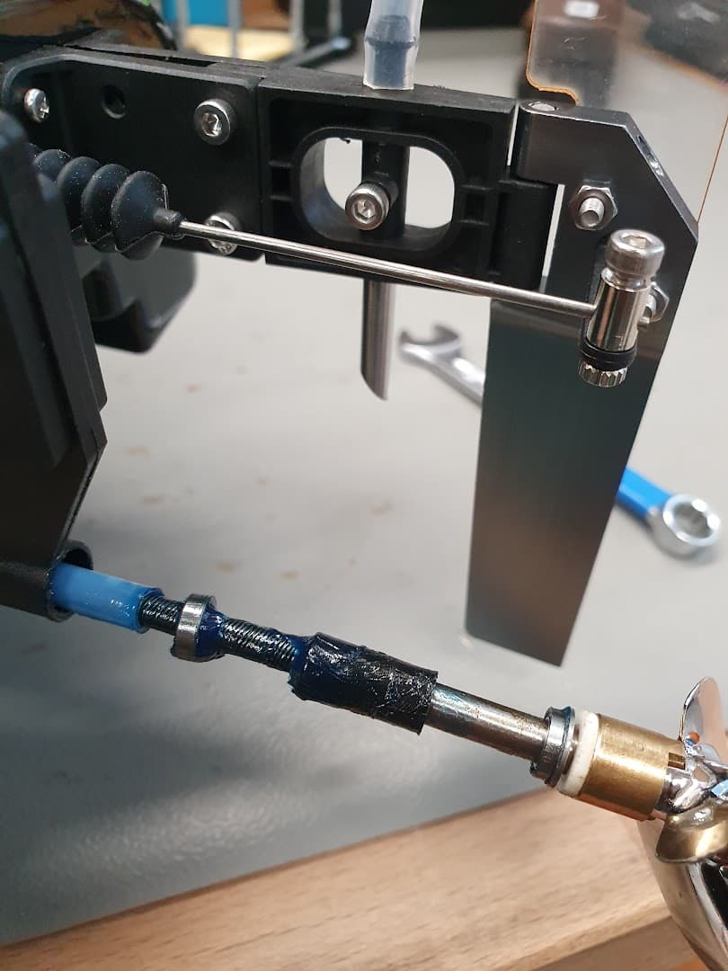
It was quite fascinating to learn the existance of all the intricate mechanical components in the flexible shaft assembly.
So here’s a pic in case you are interested:
Mounting the Flight controller and GPS
You may be surprised to learn that having a GPS module is critical in terms of having a reliable & accurate global state estimation of the position of the vehicle. And especially for a boat that can travel over distances around ~20 km, a GPS is a must for a reliable navigation!
So I decided to stick the GPS that is compatible to Pixhawk4 (It’s uBlox M8N, a very well known & reliable module) on the lower side of the cover (since the module isn’t water proof) and hope that it wouldn’t have so much Electro Magnetic Interference from the ESC & Motor sitting right underneath it ![]()
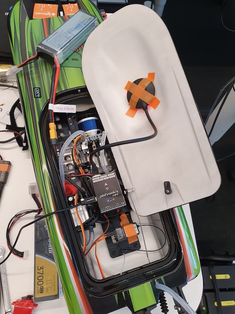
Then I also noticed that using Pixhawk4 is a pain in terms of connecting the IO pins as it doesn’t expose the Servo-style 3-pin input/output pin connections, but rather needs an IO expansion board to connect a Servo and ESC to it.
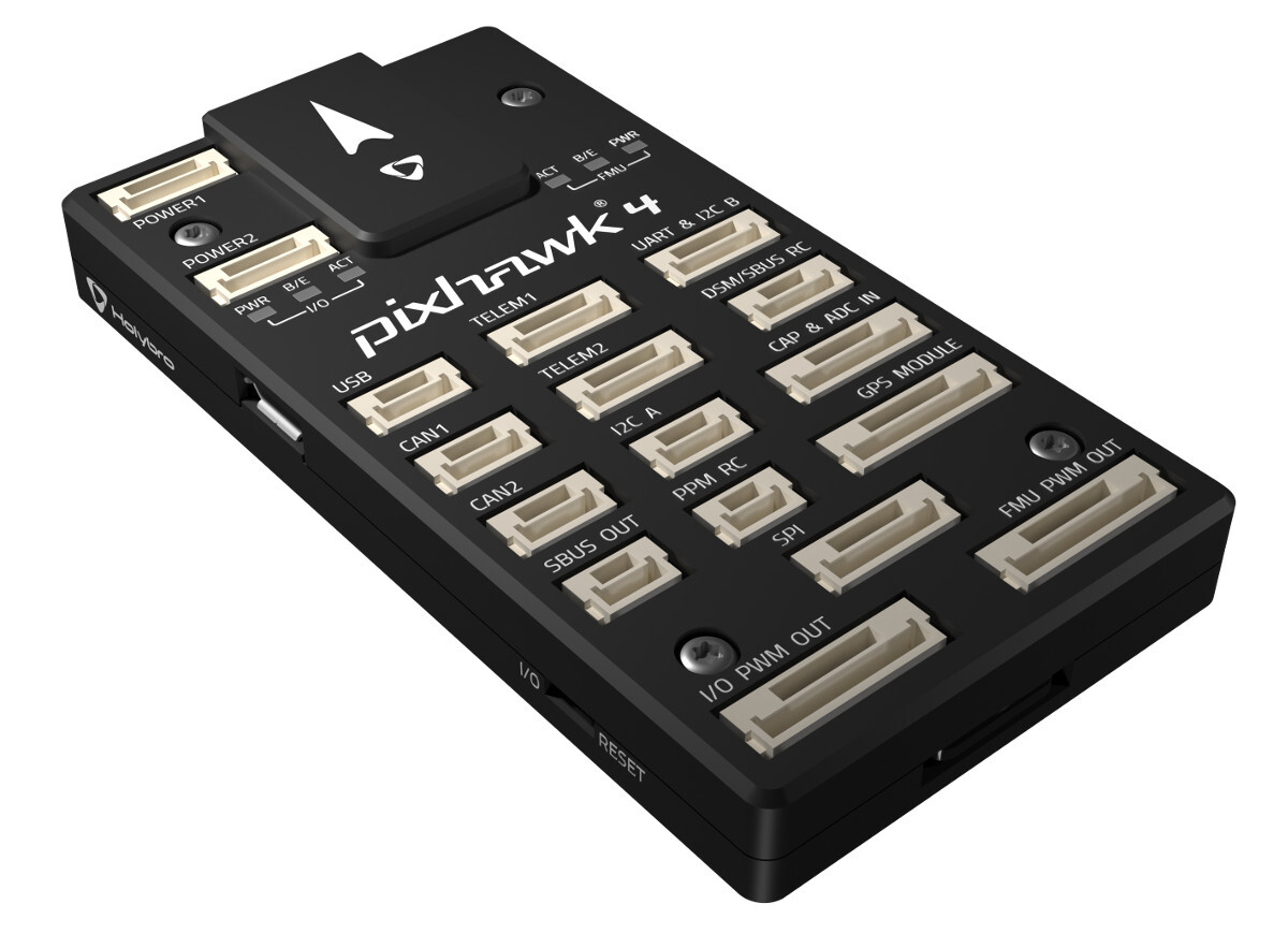
Having an IO expansion board which has contact points like the Ground potential & probably the 5V- power line and signal lines exposed was another disaster (signal interruption / electrical short circuit) waiting to happen, so no thanks Pixhawk 4 ![]()
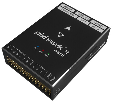
Also, Pixhawk4 is quite big as well so there was no reason to go for Pixhawk4 when I had Pixhawk 4 mini in hand, which has the output pins exposed in Servo configuration out of the box, as well as having a small form factor. No brainer! ![]()
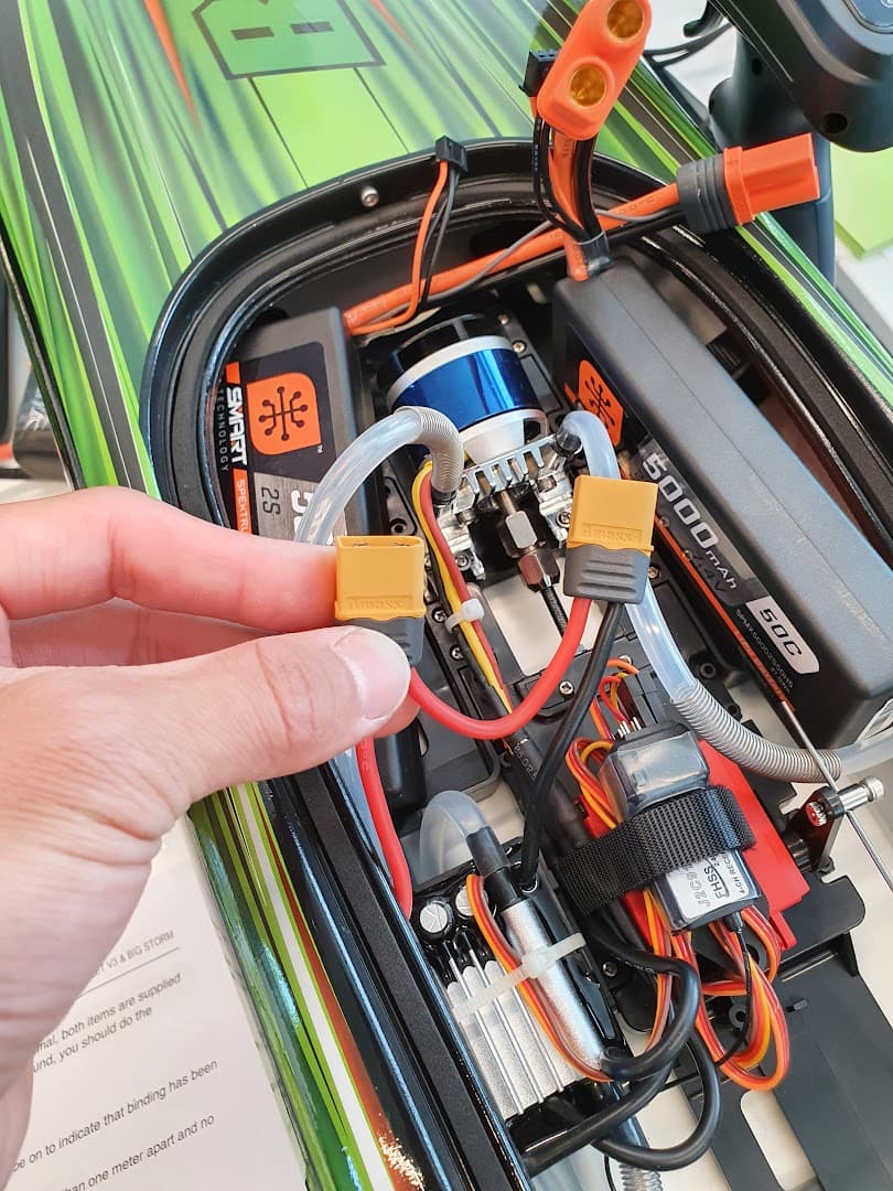
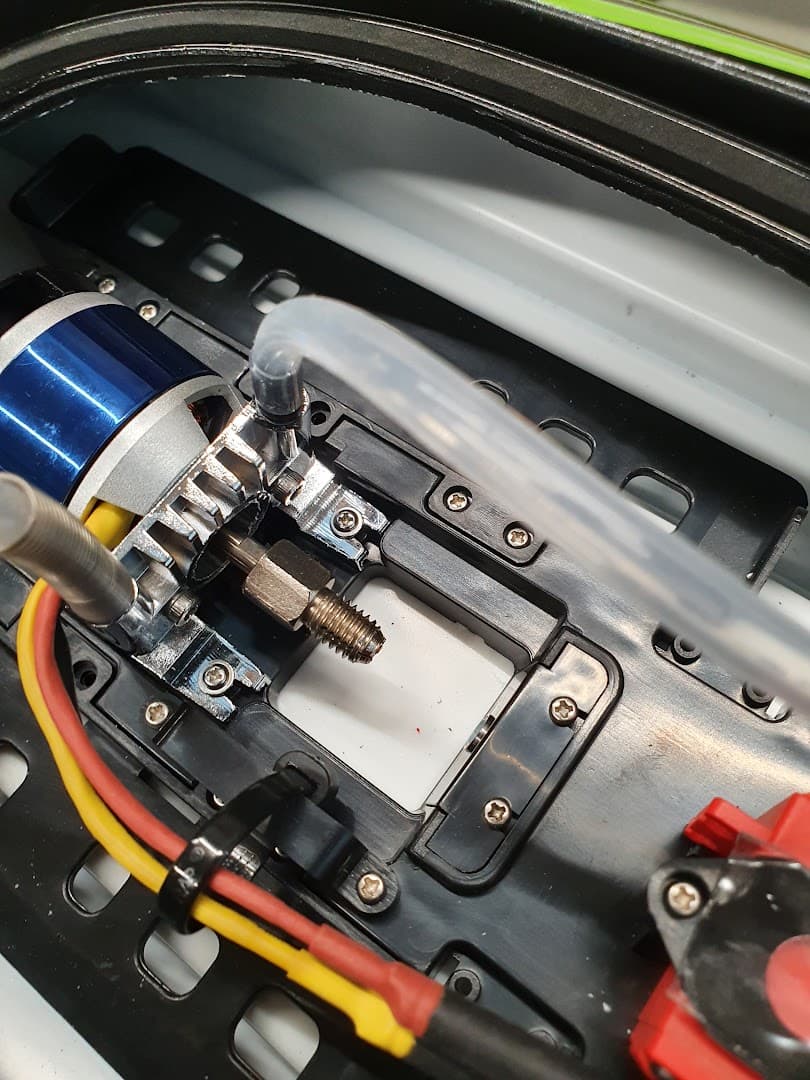
And just some wiring/cable management
Since I was moving the components around and wanted a tidy & organized internal structure, I did move around the battery connectors and cooling-water hoses.
This was done to make sure that they don’t twist together and cause unnecessary constrictions in the hose (which would degrade the water cooling capability, which then would lead to over-heating ESC and possibly killing it ![]() )
)
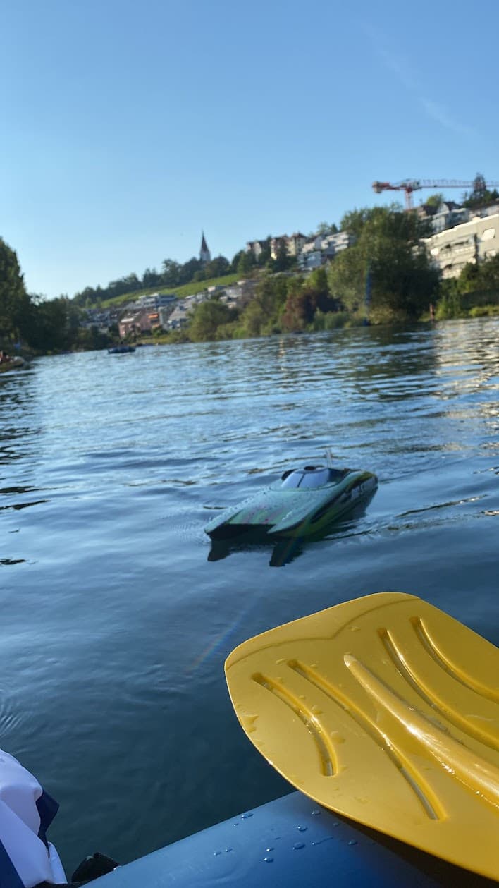
Limatt River Test
Here’s a snippet video that shows what the behavior of the boat was like. You can probably tell that it’s quite snappy and fast and reactive (especially when the speed is higher!)
")
And here’s a pic of the boat, next to the boat I was riding on ![]()
Old Receiver caveat
Unfortunately, on this first ever test I didn’t actually utilize the PX4 as the driver of the boat (the Servo / ESC were not connected to the flight controller), since I couldn’t figure out the Receiver situation.
As the transmitter & receiver that was shipped was a very old configuration, the receiver had raw PWM outputs on each of it’s pins as the commanded values of Throttle and Steering.
However, as far as I knew PX4 didn’t support such Receivers, but rather only supported PPM (Multiple channel data getting sent on a single pin/bus), which was obviously not supported with the old receiver that was delivered with the boat.
So having to take the boat on a rubber boat itself and having space constraints, I didn’t consider taking a full 10+ channel RC transmitter used for multirotors, and just went with the old legacy transmitter.
Which meant that PX4 wouldn’t be controlling the boat anymore, but would act as a data-logging device. But it was still cool, since this is the beginning!
Log Analysis
So here’s the uLog uploaded in flight review viewer. Feel free to roam around and check out the values.
And here’s the branch I used for flashing the PX4-Autopilot software. It cherry-picks the Rover rate control PR and includes a custom airframe for the boat I am using ![]()
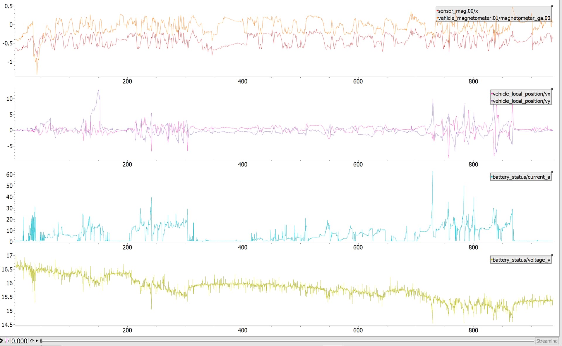
Here is a quick screenshot showing how the battery current consumption (which sometimes reached 40 amps!) seems to have some affect in the magnetometer data (as the sensor is so close to the power source).
It is also interesting to note that the boat reached 10 m/s (36 km/h!) as well, and the gradual voltage drop of the 4-cell battery.
And here’s a 3D-view that shows an iris quadrotor flying above the limatt river, where in reality the boat was cruising at the water level ![]() . I am not sure why the altitude is shown like that, that could be an interesting investigation!
. I am not sure why the altitude is shown like that, that could be an interesting investigation!
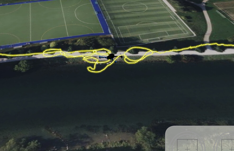
The boat is (according to the log) totally in the skies ![]()

Recap
So it was an interseting test, I have verified and checked:
- Boat’s capability (Responsiveness / Throttle sensitivity)
- Boat’s weakeness (The Servo push-rod connector slipped off from the grub-screw fastened slot, so that needs some lock-tight I believe)
- Boat’s water-proofness (Some water got in, I am still not sure how but I now know that I can’t assume that there will be no water entering the boat!)
- Battery usage (30A at 16 V equals to around 480 Watts at peak power of today’s test)
- That I can fit the flight controller and have reliable sensor data logged
What’s next?
Next objectives now are:
- Having a [rate-controlled Boat control] with throttle and servo directly actuated from the autopilot (Add support for Acro mode on Rovers with Rates Control by Jaeyoung-Lim · Pull Request #18317 · PX4/PX4-Autopilot · GitHub)
- Doing an autonomous waypoint mission in the lake with the boat
Excited what’s gonna come next as I progress with this project! Thanks for reading this post everyone! ![]()