Hello, I have designed my own autopilot hardware that is compatible with standard and related to this pinout table.
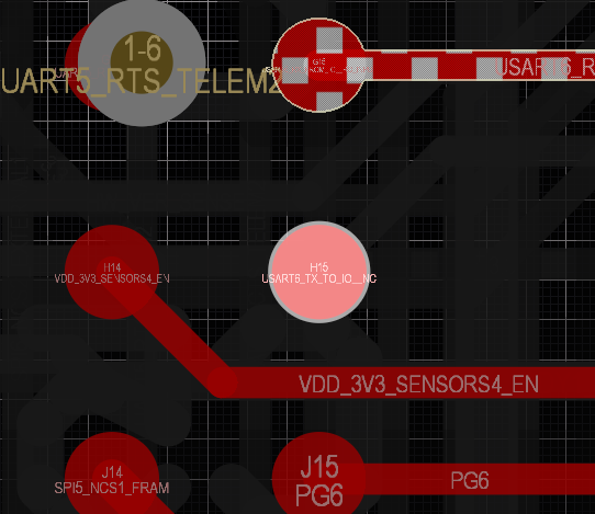
While testing my new PCB I have found that the SBUS input does not work at all. So I need some help to find out where the problem is. Please help?
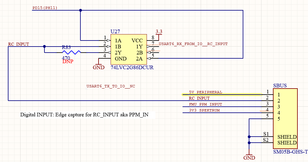
Here is part of the RC input schematic:
74LVC2G86DCUR chip inverse input signal when PD15 in HIGH, as its written in comment in table
Anyway, I have connected PD15 line directly to 3.3 voltage to be sure that its inverts signal.
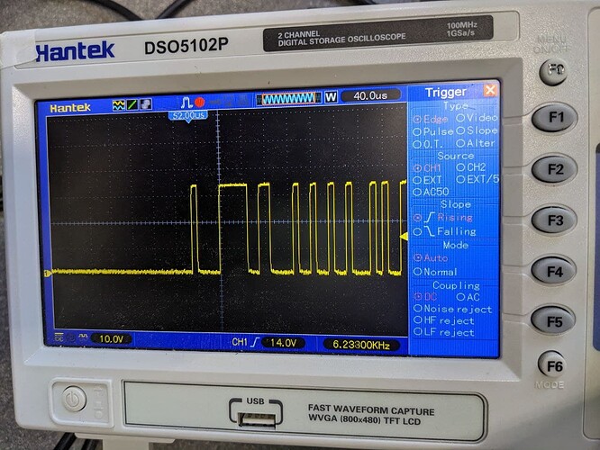
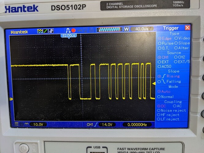
I also checked the signals with an osciloscope:
- Before the inverter
- After the inverter
SYS_USE_IO is 0
RC_INPUT_PROTO is SBUS
Here is what rc_input status shows:
nsh> rc_input status
INFO  [rc_input] Max update rate: 250 Hz
INFO  [rc_input] UART device: /dev/ttyS5
INFO  [rc_input] UART RX bytes: 224
INFO  [rc_input] RC state: searching for signal: SBUS
rc_input: cycle time: 28296 events, 179078us elapsed, 6.33us avg, min 4us max 1099us 17.836us rms
rc_input: publish interval: 0 events, 0.00us avg, min 0us max 0us 0.000us rms
And another one test, i have connect rc receiver to TELEM2 and switch RC_PORT_CONFIG to TELEM2 and it works fine. So I am shure that rc signal is received, it can be decoded. Also I have invert signal as its should be.
At the moment I have no idea what to check or change to fix it. Please help.


