Update, because I’m not sure how to remove a post. They appear to actually represent the back of the connector, so this post is void.
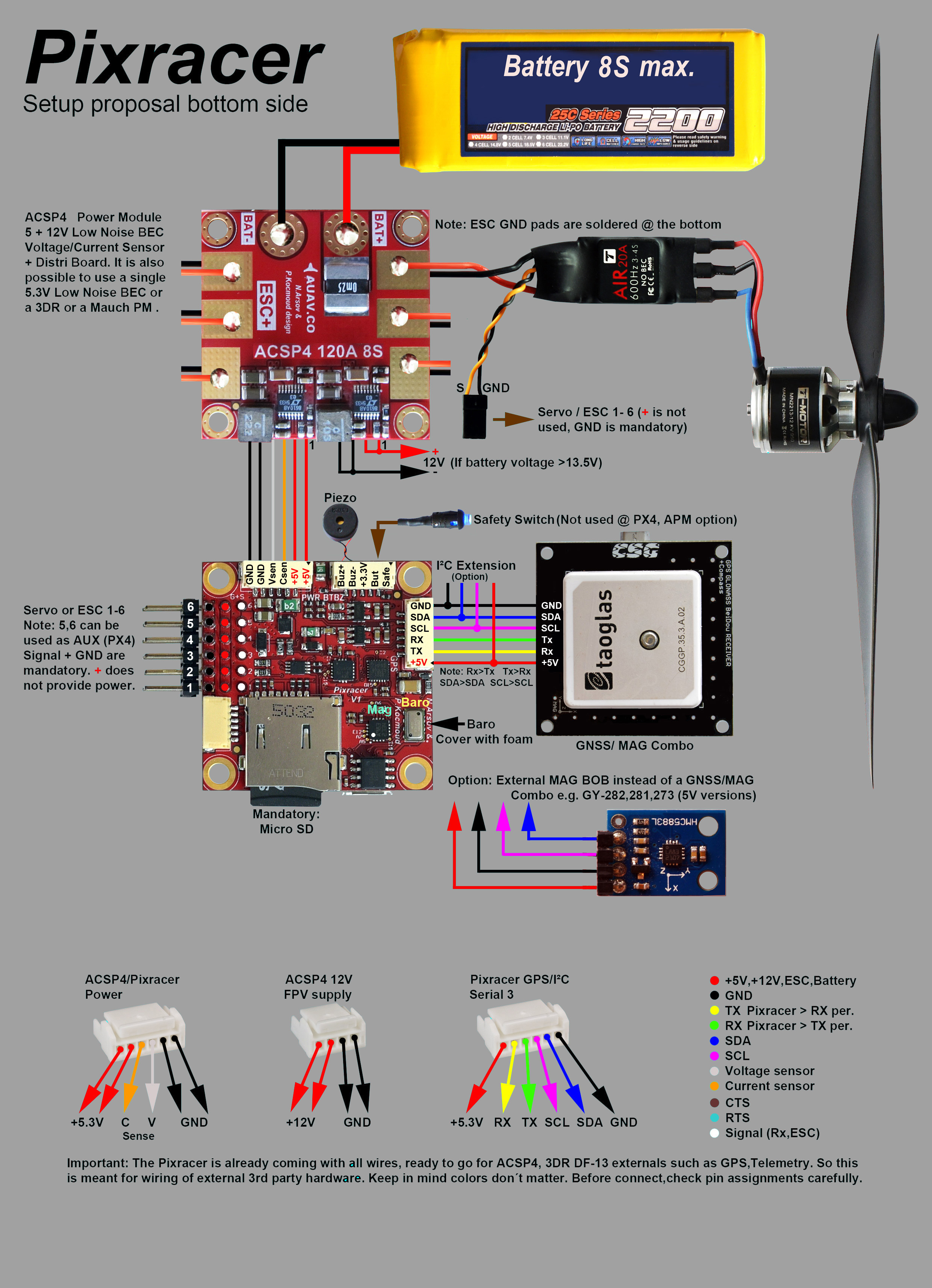
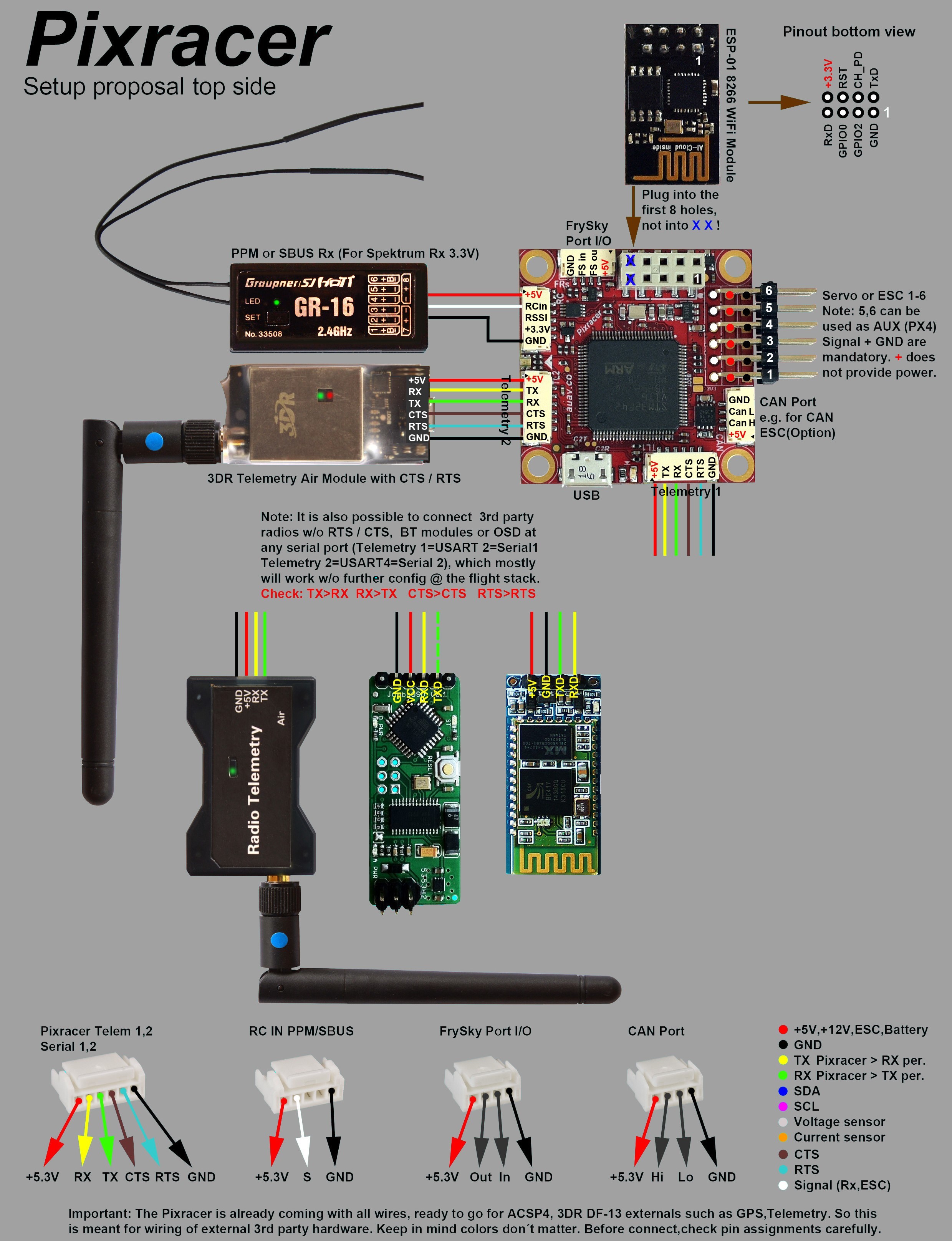
I’ve been using PixRacers for about 6 months now and often look back to the wiring guide as a reference. I often grind gears in my head looking at them and today I think I’ve located the reason. If you look at the pictures for the “Main Setup” you may notice some things don’t seem quite right, Redirecting to latest version of document (master) namely the pinouts. The ones for the board ports themselves are correct, with the port on the top of the board the v+ is to the left and The clip is on top. If you look to the diagram showing the connections from the connector themselves (bottom of the pictures) they’re actually a mirror image, or what the back of your connector wiring should look like. The v+ is the the left of the front of the connector, which is actually the right when connecting to the port, so if you wired your connectors based on those images(of the connectors) it would be gnd->v+, and v±>gnd. This isn’t a major issue by any means but I figured I’d bring it up. Attached are the images I reference.
@jcharette thanks for the note! I’m pinging @hamishwillee @barzanisar, hopefully they can have a look.
Hi @jcharette,
Sorry for the delay, was away on holiday!
I’m feeling a bit slow today, so can I please first confirm the problem and expected solution.
I think you are saying that the pinouts on the boards are correct. So in top-side diagram FrSky port has +5 on our RHS close to the wifi module. If you were looking at that port from the side into which you connect you’d see it on the LHS.
At the bottom of the top-side diagram that same port (3rd from left) is shown with the 5V on the LHS. But what I THINK you are saying is that the image is of the back of the connector. Someone actually looking at the connector would see the other side, so the 5V is actually on the RHS from the user perspective. Ie the lower diagram is wrong for all the connectors. Is that correct?
The best solution would be a new diagram showing the front of the ports at the bottom with the correct labelling, but I don’t have the base images to regenerate this. Suggest the least confusing option is to just delete the connector diagrams at the bottom and move the colour key up.
Does that seem reasonable @JulianOes @jcharette ?
1 Like
Honesty I dont see this as a real issue. I just misinterpreted the image initially. Maybe something as simple as a note stating that it’s the back of the connectors but I don’t think that’s even necessary. Thank you for the responses.
1 Like