I’m trying to set up a FrSky telemetry link using the DIY method with the MAX3232 chip breakout board from eBay as per the instructions in the GitHub page linked to by the FrSky Telemetry Docs.
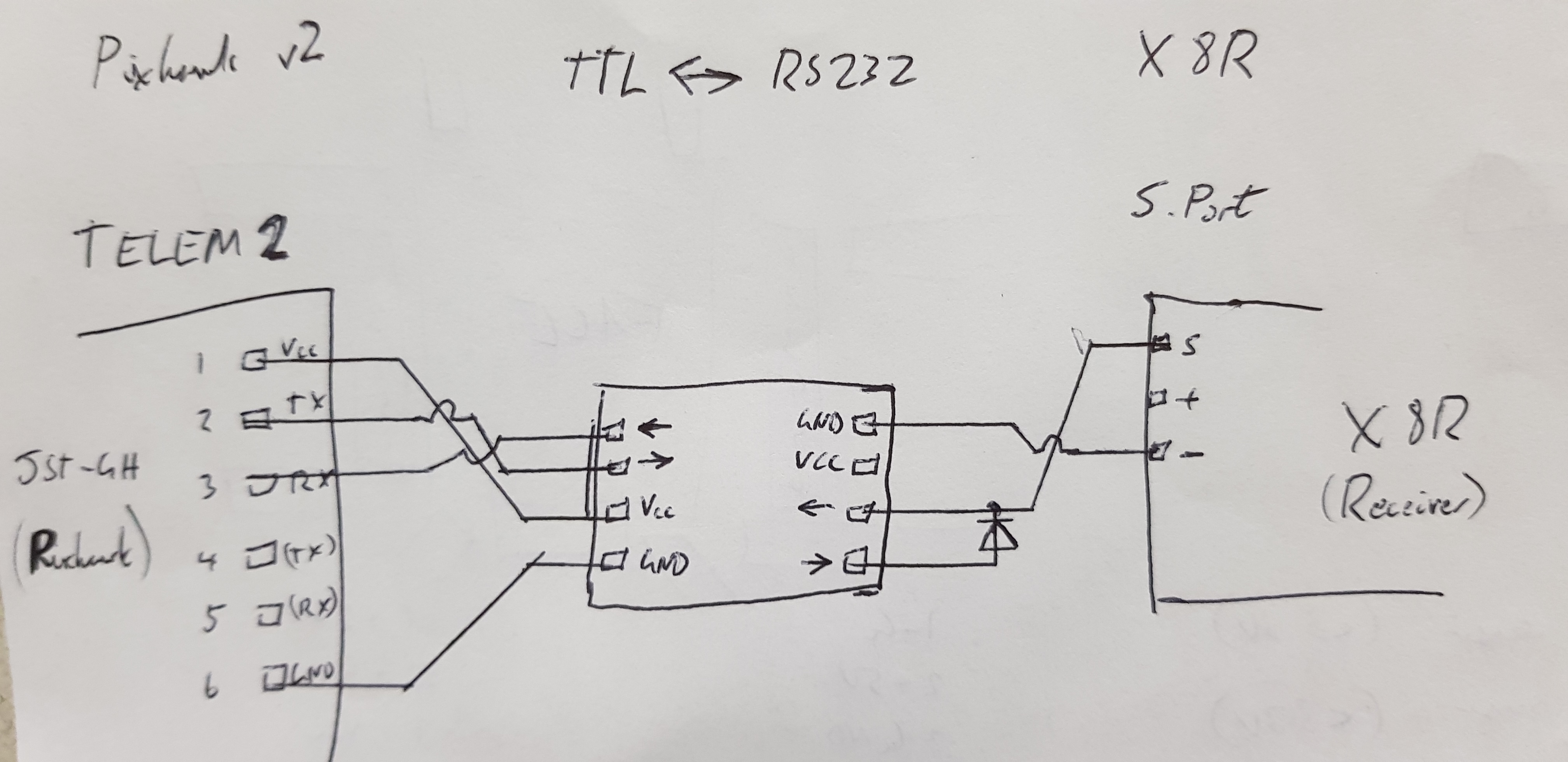
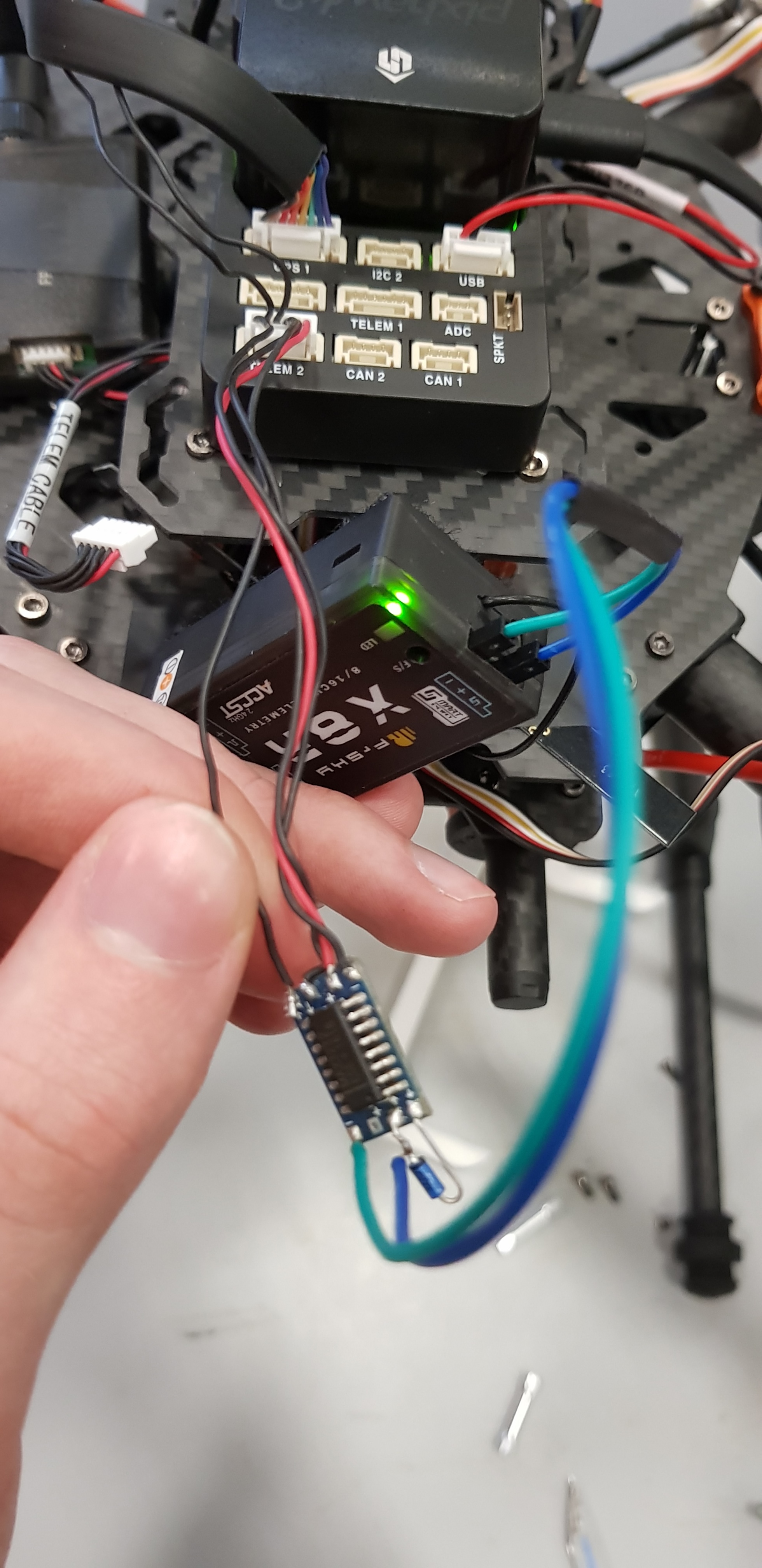
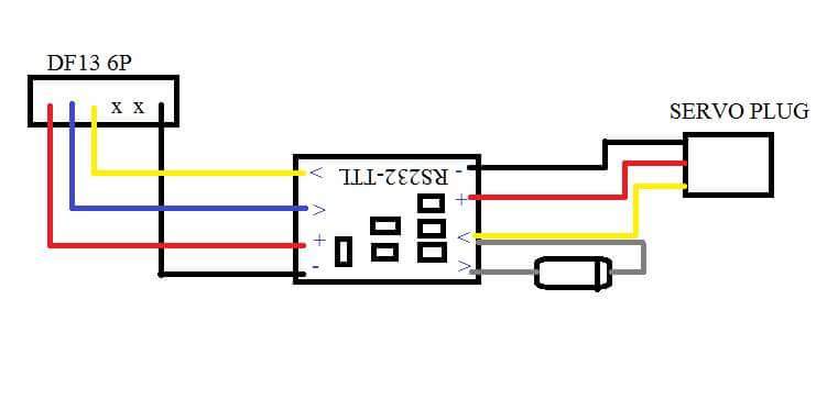
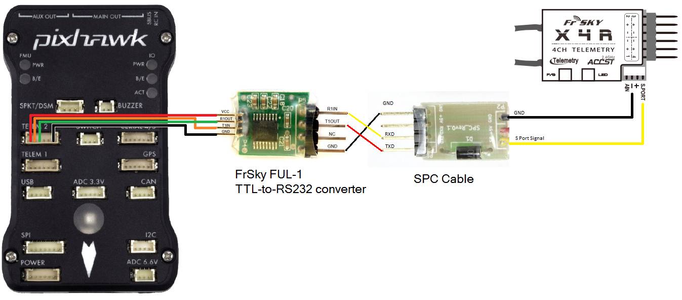
I’ve soldered together the cable as shown in the photos and circuit diagram below and connected it between my receiver’s S.Port and my flight controller’s telem2 port, set the SYS_COMPANION parameter to ‘Frsky Telemetry’ in QGroundControl and used my transmitter to search for sensors but I can only find the RSSI and RxBt sensors from within the receiver itself. All the sensor feeds from within the Pixhawk seem to be missing.
Really, I was just wondering if anyone could tell me if I’ve missed something like a parameter that should be set or made any other obvious errors that would make everything work as intended?
(Note that I’ve purposely omitted the Vcc cable on the receiver side after reading the GitHub thread related to setting this up on a Pixracer. I’ve checked with a multi-meter and the two V+ pins are electrically connected so this shouldn’t be a problem, power being supplied to the chip from the pixhawk end and to the receiver by its connection to the RCIN port on the Pixhawk.)
@robwaat I am trying to connect an X8R to a pixHawk2.1 (cube) like you. I am a bit puzzled because I saw different wirngs on the net. I tried first to connect SBUS to RCin but it does not work and I cannot find out why? Do you have an explanation on your side? Does it mean that the only way is to connect SPort to a Serial (Telem 1 or 2)?
Regards
Just throwing in a thought. Are you connecting to the Smart Port? When you say S port is that the SBus? I use a Pixracer and RCin comes from the SBus on an X8R without issues. Amazing - everything in on one wire!
I am curently struggling with the FrSKY special port on the Pixracer under QGC -have been for some long time. The FrSKY port, I read should have Tx and Rx wired together and then taken to the Smart Port (half duplex comms)
I do not see any FRSKY parameter or even SERIAL parameter in my bang up to date firmware!!
Any mising parameters has to be a “fault” of the firmware I am sure. I’m even buying another Pixracer just to see if I updated and overwrote parameters on first use (on TWO Pixracers!) So be aware that the firmware may be a work in progress at any time.
I’m waiting for another Pixracer in the next couple of weeks. I found one at a good price, even though I don’t really need one! That shows how frustrated I have been.
This way I get to check BEFORE updating any firmware whether I see an FrSky parameter. If not, I can complain to the vendor. But if it’s OK, then I’m on a different path: check what firmware is present and see if I can load this into my curernt Pixracers, if I can locate it.
Will post an outcome when it arrives.This is a add in (butt-in?) to your discussion. I have a discussion running under the title “Pixracer Has No FRSKY or SERIAL Parameter Listed in QGC”
I managed to hook up a companion computer running mavros and have it report the telemetry to QGC via wifi, so the need for the controller feed just wasn’t there.
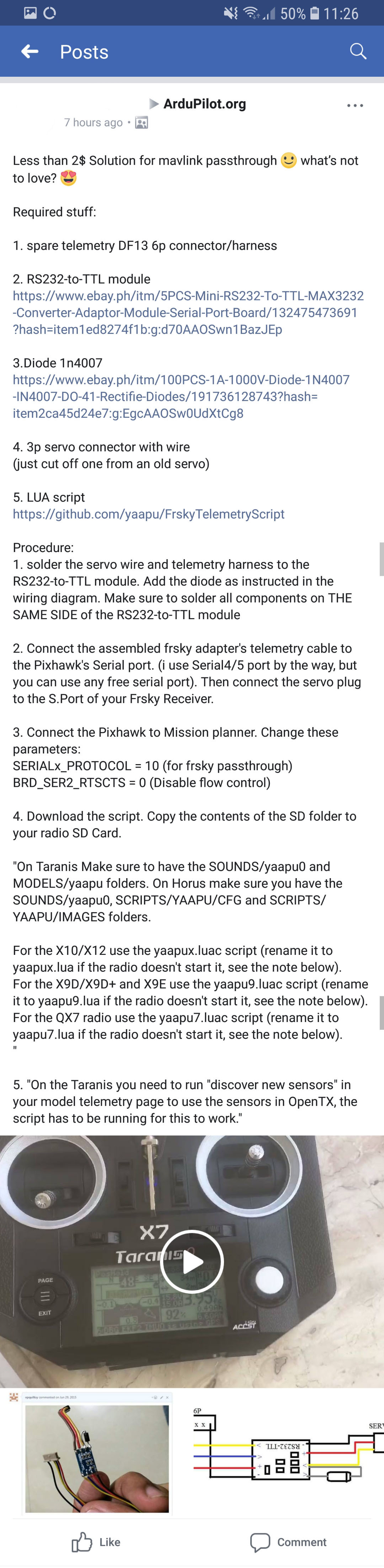
That said, shortly afterwards, I did find a post on a facebook group that seemed to have some success (see attached images). I never tried it myself, however.
I am pretty sure that these parameters (which are in the online documentation) are not available in 1.8.0 or 1.8.1 Firmware. I believe they were a post-1.8 change. Perhaps they will be included in 1.9. So I doubt you will see them even if you purchase another flight controller.
I have similar problem. I wanted to make this type cable by myself. bought all kinds of RS232 to TTL module using SP3232EEN or MAX3232 chip. they both do not work. we have test it by a oscilloscope, the wave is not correct. I think it should be easy. at last I give up and bought a cable from below link.
it works fine.
The max232 does work. But it must be wired correctly with all connections on the top side of the board. I found out the hard way that the connection on the bottom are different, even though they look like an ESC where you can solfer power either way.
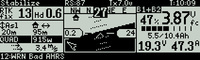
The Yaapu LUA for PX4 stack is now available in beta. You have to use a Teensy as @Sal_Calderon mentions. I have it working a the X9D+ and Q X7 and so far so good. Sample graphics below.
You saved my day mate, no way I could have realized this by myself. I soldered stuff on bottom first and it didn’t work, after reading your comment and reworking, boom telemetry.
I also put two 1N4007 diodes on the +5V wire to MAX3232 board to drop the voltage a little, as I remember reading somewhere else that feeding it with 5V somehow fries the chip over time. I don’t know if it makes sense but it doesn’t seem to do harm anyway.
I don’t know if the ground is isolated in the MAX3232 chip between both sides, if not, there is a ground loop (FC - MAX3232 - RX - FC). I’d just keep the ground wires and keep wires close to each other for now.
