I have searched the forum and elsewhere but haven’t found a clear answer on how to use a PWM pin ( or other?) as a digital output ( would be curious about enabling input too, but not needed at this time)
Would anyone be able to point me to some documentation or send me an example code that does this?.
Is this something that can be done via the configuration files in init.d or is it something that needs to be hardcoded and compiled?
I don’t think there are any user configurable GPIO pins. Look at px4fmu_led.c to see how to write code which uses outputs pins, and any board_config.h (in src/drivers/boards) to see how the GPIOs are configured.
Thanks Mark
If I wanted to use an AUX OUT pin, would it be enough to not enable PMW_AUX in the init.d/ startup script and then develop an application ( I mean such as https://dev.px4.io/tutorial-hello-sky.html) that subscribes to whatever channel is meant to drive the digital output?
Or are PWM_AUX pins always controlled by the main PX4 application, i.e. not available for other use?
look in fmu.cpp to see how the AUX pwm output pins are handled. You can probably get away with disabling all AUX pwm outputs, but note that there are other things like camera trigger which can be set up to use those pins also.
You can probably just edit rcS to start fmu.cpp with no (or less than 6) PWM outputs enabled. Look at the mode_pwm options. That’s assuming you’re using fmu-v2, v3 or v4
I could not manage to include the last boar_config file, due to some error while building my function.
I tried to use the definition from drv_gpio.h # define GPIO_SERVO_6 (1<<5) /**< servo 6 output */
but I think it is probably the wrong one.
I also inserted the set FMU and Set AUX_Mode, but it did not work.
(It also threw me an error. I think pmw4 was not know. - and I did not have a camera part in this referred code??..)
But regarding this, as far as I understand the webpage, I should be able to use the aux pins 5 &6 anyway due to default virtual pin setup.
Also the commands px_arch_gpio don’t exist for me - why? Is there a way to determine which board I exactly have oir what am I missing? I used:
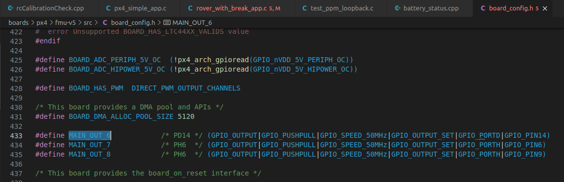
This defines the output modes of the GPIO pins you are interested in.
These lines specifically enable GPIO push-pull output on the MAIN_OUT pins 6 and 7 of the Pixhawk 4 mini.
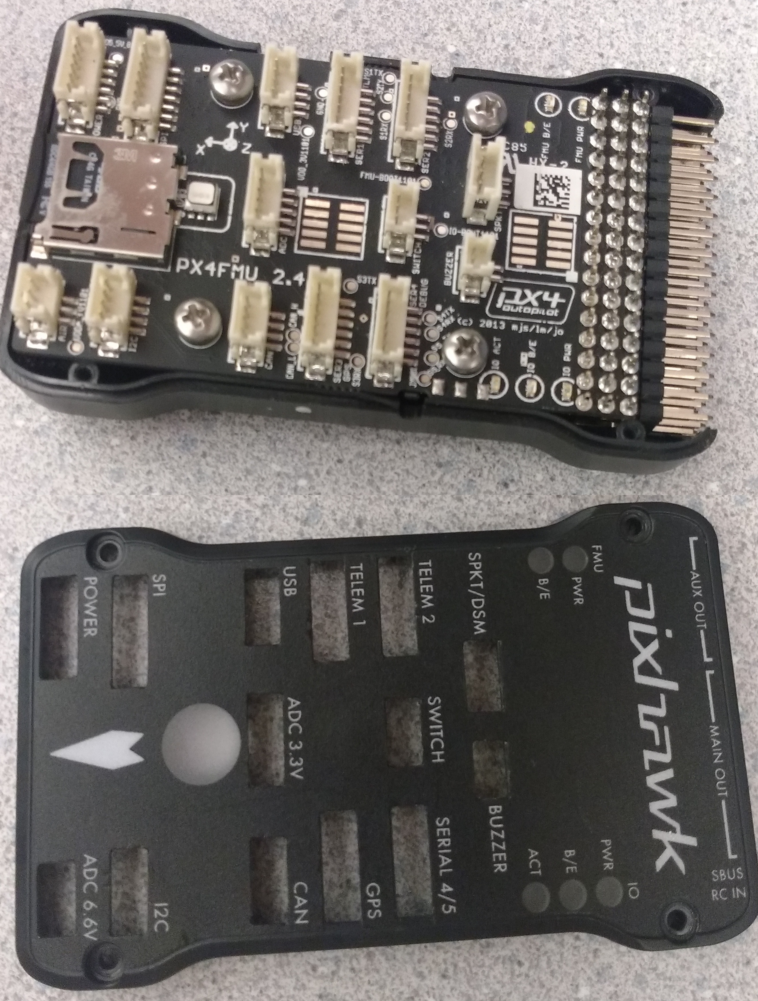
According to: Pixhawk4Mini_pinout, these pins correspond to FMU_CH6 and FMU_CH7,
which corresponds to “Port D, Pin 14” and “Port H, Pin 6” according to: FMUv5_stm32_pinout
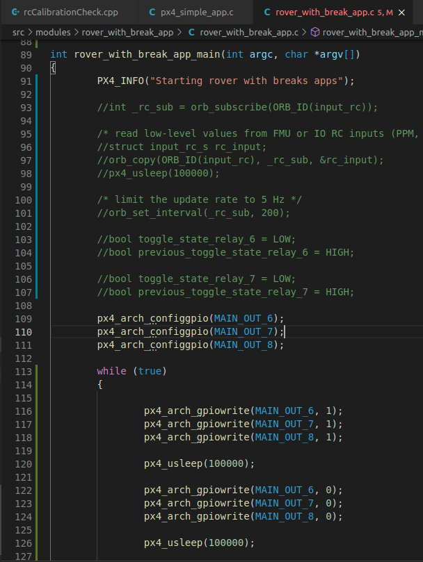
Now, in your own app like px4_simple_app.c from Hello Sky Tutorial, add the following code to configure the pins first:
@Murray_Louw Im actually trying your method now for Pixhawk 4. I think I am configuring it right but not able to control the gpios… hmmm. Im trying to make ti blink
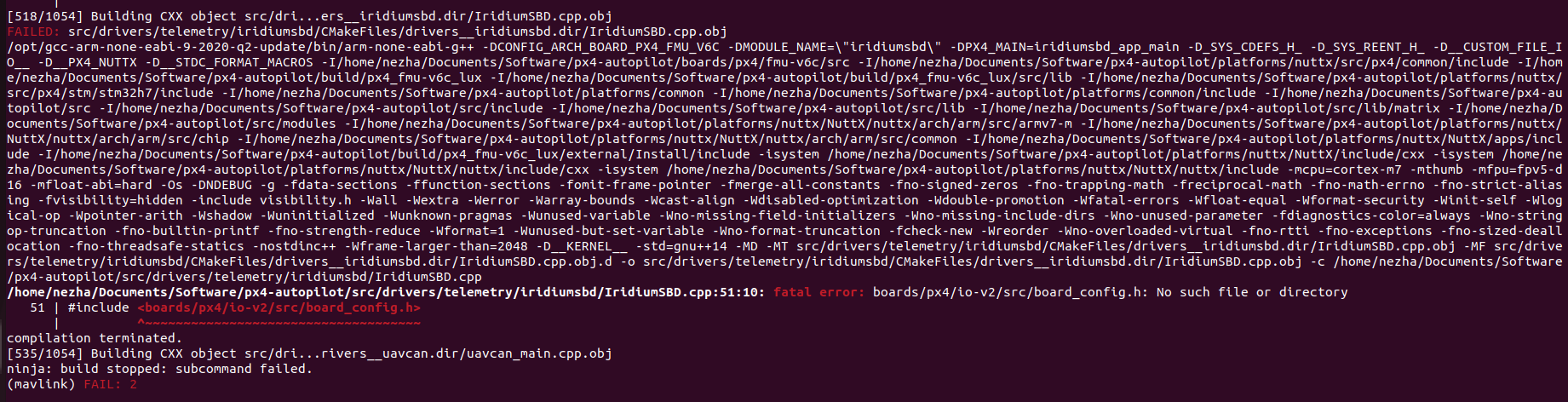
I’ve been able to control all FMU GPIO pins successfully, but I was wondering if its possible to control the GPIO pins for the IO processor (px4io). I’m using V6C hardware and I’m getting an error when I’m trying to use these pins.
Here’s what I’ve done:
I’ve added this definitions in boards/px4/io-v2/src/board_config.h to make it more readable: