The situation is as follows
At the beginning, I found that the mixer is running in two functions:
PX4FMU::cycle() in “px4fmu.cpp” and
mixer_tick(void) in “mixer.cpp”
at the same time.
After a series of tests, I found the function mixer_tick() make the pwm output.
then, I found the parameter “SYS_USE_IO” in group “system” in QGround. I changed it to 1, and it can’t provide PWM while running PX4FMU::cycle() and stopping mixer_tick().
It must lack a function to init the io and pwm hardware when I changed the parameter.
In addition, two functions includes this sentence:
up_pwm_servo_set(…);
this is the function to set pwm duty ratio.
the structure here make me confused, could you help me?
I’m sorry, I find it …
there’s a list in the same file…
The param SYS_USE_IO is mainly used in the startup to decide if the [px4io] (https://github.com/PX4/Firmware/blob/master/src/drivers/px4io/px4io.cpp) or the fmu driver should be used.
For the Pixhawk hardware, the px4io driver is used for the “MAIN” pins while the “FMU” drives the AUX pins.
The mixer lib and up_pwm_servo_set function are then both reused in px4io and fmu.
Does that clear things up? Or what exactly are you trying to achieve and with what hardware?
o, Thank you very much. It’s clear.
I’m using hardware “pixhawk”.
Thank you again.
Could you help me another question?
this is in the ‘mixer.tick()’
is the first “up_pwm_servo_set” update the pwm value to the AUX_OUT ?
and this is absolutely same as the code in the file ‘fmu.cpp’, don’t they conflict ??
In addition, I find the hardware connection, It seems that STM32F4 controls the IO in STM32F1 by USART ? Is it the sentences followed ? What I understand is correct ?
I can’t show two picture at the same time as a newer
this is the code in the ‘fmu.cpp’

You are right that px4io.cpp communicates over UART to the IO processor which is an STM32F1. THe PWM call is therefore executed there. The MAIN pins are wired the IO (F1) while the AUX are wired to the F4. The up_pwm_servo_set() commands therefore don’t interfere, however the code is shared (but the defines of the pins differ).
When I download the firmware, the part from ‘fmu.cpp’ is downloaded to the F4, and the part from’mixer.cpp’ is downloaded to the F1 ?
If the real situation doesn’t run like that, instead, all firmware download into the F4, how to avoid the conflict. I think BOTH of the sentences changed the SAME channels using the SAME code.
Well fmu.cpp and px4io.cpp both run on the F4. While fmu.cpp accesses the AUX pins directly, px4io.cpp talks to the F1 over serial. On the F1 runs px4iofirmware which sets PWM.
It’s not quite straightfoward, I should probably add a diagram in the dev guide which explains it a bit more.
What again are you trying to achieve?
sorry, I ignored it.
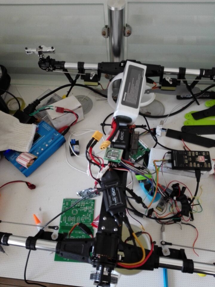
We are going to make variable pitch muticoptor test, and wanting to use pixhawk as the controller.
We encountered a problem. It’s hard to adjust the pitch of four blades to keep them zero when it takes off. so, we add parameters to adjust and we need a new mixer method. However, We can’t get the job done.
Could you explain how the code in ‘mixer.cpp’ works ?
The function execution order is as follows:
user_start(int argc, char argv[]) ****************** //in ‘pix4io.cpp’
controls_tick();//in function ‘user_start’ in file ‘pix4io.cpp’
mixer_tick();*** //in function 'controls_tick() in file ‘mixer.cpp’
Then, here in mixer_tick(), there’s code as follows ------------
Uploading…
As I post here, how the function up_pwm_servo_set() in ‘px4io’ part work ? which part of hardware does it control ?
I can’t upload the picture because of the Internet unstable.
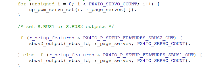
the code in ‘mixer.cpp’ is as follows
if (mixer_servos_armed && (should_arm || should_arm_nothrottle)) {
	/* update the servo outputs. */
	for (unsigned i = 0; i < PX4IO_SERVO_COUNT; i++) {
		up_pwm_servo_set(i, r_page_servos[i]);
	}

	/* set S.BUS1 or S.BUS2 outputs */

	if (r_setup_features & PX4IO_P_SETUP_FEATURES_SBUS2_OUT) {
		sbus2_output(_sbus_fd, r_page_servos, PX4IO_SERVO_COUNT);

	} else if (r_setup_features & PX4IO_P_SETUP_FEATURES_SBUS1_OUT) {
		sbus1_output(_sbus_fd, r_page_servos, PX4IO_SERVO_COUNT);
	}
The question comes, what the main three sentences control ?
what the function ‘up_pwm_servo_set(i, r_page_servos[i])’ control ?
Sorry, I need to go to work.
See you later ~
Thank you very much.
It’s hard to follow what you actually are trying to adjust.
Can you explain what the change functionally should look like? Then I might be able to tell you where it should belong.
Sorry, maybe my English is not very well…
The situation is as follows :
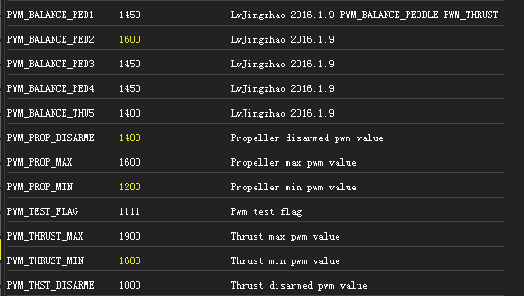
At first, variable pitch multicoptor needs more parameters to adjust the pitch. In addition, we should add parameters about the thrust. It’s like that
The first question is where should I add the function for changing parameters ? I don’t think the way we change the code is very well.
The test is as follows, could you help to find the problem ? It must be wrong somewhere.
- We add the sentences in the function cycle() in file ‘fmu.cpp’

It works well. Then we think the function is running in a thread
2.Then we add functions about changing the parameters, while the parameters have been registered.
However, it works not very well.
We make a summary about it :
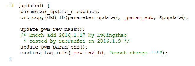
When we read the parameters from qground, we can sure, the function ‘update_pwm_param_eno()’ is excuted. In this function, It works like the follow sentences:

However, when we change the parameters from the qground, the pwm output can’t changed by the parameters.
3.We test the function mixer_tick() in file ‘mixer.cpp’ which is associated with px4io, find that the pwm output is controlled in this function. Why the function ‘up_pwm_servo_set()’ in ‘fmu.cpp’ CAN’T WORK? It seems running at the same time.
What makes me coufused is that, when we change the Parameter USE_SYS_IO to 0 and restart, it works, because when I changed the parameters, the output changed. At the same time, the qground CAN’T RECEIVE the mavlink message…
I fall into disorder …
What I understand now is that
- SYS_USE_IO select whether use hardware PX4IO.
- The output in FMU is the AUX_OUTPUT.
- The output in PX4IO control the MAIN_OUT
- The FMU transfer commands through serial to PX4IO.
Question:
- up_pwm_servo_set() is excuted in two parts, PX4IO and PX4FMU. They are absolutely same.Then which is work ? which part of hardware the function controls ? AUX_OUTPUT ? How they can keep non-interfere ?
Maybe, I need more test. I’m trying it.
What again are you trying to achieve?
Sorry about my disapperance.
I have finished my goal.
Thank you for your interpretation about the relationship between px4io and px4fmu.
Maybe the process we try to modify the cod is a little confusion, and we made much mistakes.
Because of the position error of the servor, we need to add several parameters to adjust the paddle which is controlled by four servos. While, we need to change the style of parameters original. Another demands is to adjust the parameters convenient.
(Hoping that you can understand my pool English ^_^)
Now we add the parameter refresh in the ‘fmu.cpp’, and is using the AUX_OUTPUTS…
Can I see how you achieved this? I am also trying to accomplish the same task by offsetting two of the servos for the variable pitch quadcopter.
In conclusion, we need more parameters and little code to adjust the different paddle, or the actuators.
The attitude control for flight is completely same.