I’m developing a custom flight controller, based on the STM32F765VGT6 (1 MB flash, Cortex-M7) . Before production, I’d greatly appreciate your feedback on my schematic and design to ensure compatibility and reliability. Thank you for your time and expertise
Hardware Overview
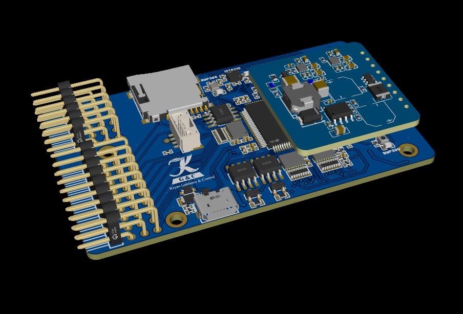
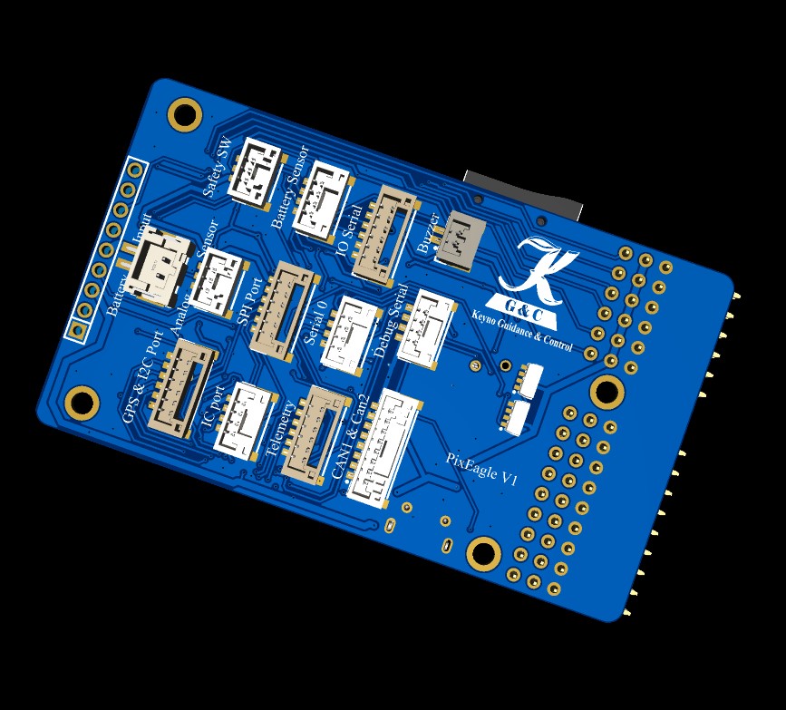
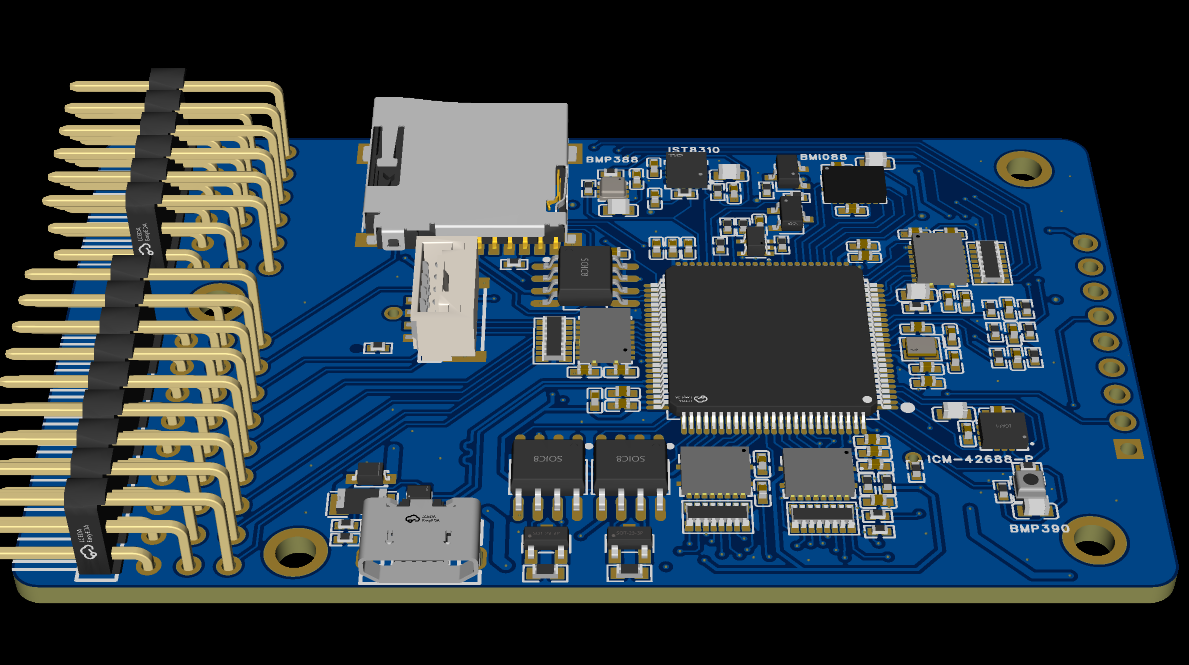
MCU: STM32F765VGT6 Sensors:IMUs: BMI088 (SPI3, shared), ICM-42688-P (SPI1) Magnetometers: IST8310 (I2C1, shared), MMC5983MA (SPI2) Barometers: BMP388 (I2C1, shared), BMP390 (I2C2) Storage: FM25V01A-GTR (FRAM, SPI3), MicroSD (SPI4) Connectivity: 8 PWM outputs, 2 CAN buses, UARTs (telemetry, debug, SBUS), TXS0108ERGYR level shifters Schematics and pin assignments are in my GitHub:
The idea is, FC only focuses on the critical stabilization task while the companion computer looks after navigation and removes a lot of burden from the processor, which uses a high-performance MCU, more information at www.keyno-gc.co.nz
So, personally I will opt for a different MCU…more capable in memory, just remove the IC for sbus coz F7 and H7 can handle sbus, are you opting for JTAG or DFU for flash the MCU? I think you don’t need add two magnetometers on the board coz usually the internal on the PCB it’s affected by vibrations and emi. Add to the boot pin a 10k res connected to GND and check the correct value about the resistors for the current and voltage sensing..
No mandatory analog connector.
For flash I can suggest JTAG footprint by tag connect 2030 footprint.
The design it’s a little bit confusing due many connection .
Thank you for your valuable feedback on my design. Below are my responses to your comments, along with some follow-up questions for clarification:
1. MCU Selection & SBUS Reliability
I opted for the STM32F765VGT6 (mid-range Cortex-M7) to balance performance and cost, delegating advanced AI/sensor fusion tasks to the companion computer (RPi CM4/ESP32-S3).
You mentioned that SBUS is more reliable on H7/F7 MCUs. Could you elaborate on why? Since SBUS is a simple serial protocol, I assumed compatibility across most STM32 series. Are there timing or hardware peripheral considerations I might have missed?
2. Debugging & Redundancy
JTAG/SWD + DFU: These were included to ensure programmability in cases where the MCU lacks a bootloader (e.g., raw chips).
You suggested removing one magnetometer since drones often rely on external compasses (e.g., GPS modules). Which one would you recommend keeping?
The MMC5983MA (SPI) offers higher resolution, while the IST8310 (I2C) is more common in PX4 ecosystems.
Should I also remove a barometer and add a third IMU instead, or is dual redundancy sufficient?
3. Power Design
Dual MIC5332 LDOs: Used to provide clean, low-noise power to sensors and MCU.
Battery Voltage Sensing: A 10kΩ/1kΩ divider (11:1 ratio) scales battery voltage (<3.3V) for ADC measurement, with separate analog inputs for voltage and sensors.
4. Footprint Example
You asked for a 2030 footprint example. Did you mean a specific component (e.g., crystal, capacitor) or a PCB dimension standard (e.g., 20mm × 30mm)? Please clarify, and I’ll provide the relevant details.
STM32F7 and H7 families of microcontrollers have built-in capabilities to handle both inverted and uninverted signals for UART communication.
Debugging:
As mentioned you can use the TC2030 footprint instead of add a connector for the flash bootloader and the firmware, the address for the bootloder its different from the address of the firmware.
I’ve reviewed your feedback and made a few changes based on your suggestions. I still have a couple of questions, though.
First, regarding your comment on the STM32F765 series: since I’m using this microcontroller, do I still need a U74LVC1G14G single-line inverter for the SBUS?
Second, I’m having trouble with the pin arrangement for my connectors. Some GPS modules, for example, have a separate I2C port, while others have a single connector that includes both serial and I2C. Is there a standard or recommended way to arrange the pins? For instance, should all serial ports be arranged in the same order (e.g., 5V, TX, RX, and GND)?
I’ve also moved all my buck converters and LDOs to a separate board to improve signal integrity, as I’ve found the ESC power supply to be unreliable and noisy.
Good day, you can remove the U74LVC1G14G IC…no needed in F7 and H7 MCU, you can add only a 220R as you are working with a TIM channel. About the connector for GPS, you can do in this way a JST-GH 6 pin…5V-TX-RX-SDA-SCL-GND.
Check also a good pcb stackup…i think due the density you must use 6L.
So.. MCU VDD pins rquire caps like datasheet, all SPI CS pin must have a 10k pull-up resistor, no need analog sensor, ive some concerne about your SBUS design, in can transceiver miss a 120R. The schematic its caotic.