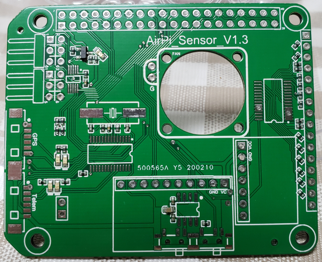
The whole design contains two PCB boards, managing power supply and sensors independently. Here I mainly talk about the part of sensors. It is built and tested it with Raspberry Pi 3B+ model. It should also be compatible with 3B and 2B, but I’m not sure whether it is the best solution on 4B or not.
It contains:
1x MPU9250 on spidev0.0
1x MS5611 on i2c1
1x PCA9685 on i2c1
1x ADS1115 on i2c1
1x SC16IS752 on spidev1.0
1x REF5050
other peripheral circuit, such as SBUS inverter and reference voltage source.
Provides functionality of:
Accel+Gyro+MAG
Barometer
16x PWM outputs at 12bit resolution
4 ADC channels that monitor battery voltage, current, analog airspeed sensor and probably board 5V system power supply
3 UARTs. One for SBUS RC input, one for GPS and one for telemetry.
There still can be a free I2C bus available for external mag sensors combined with GPS module. Or some other I2C sensors supported by Pixhawk.
Note that current sensing works only if external sensors connected. Boards itself has no ability for monitoring current. I say that just because possibility exists.
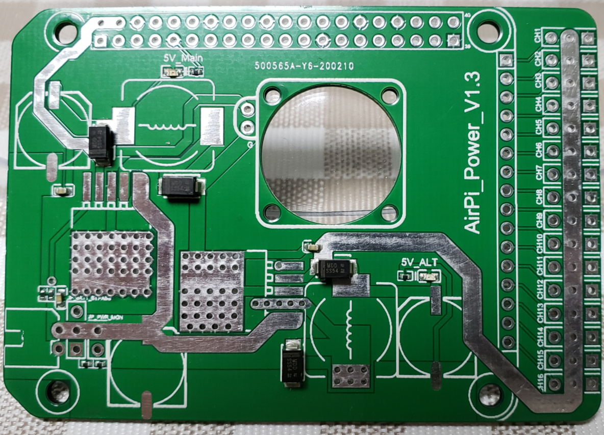
The power-module contains two sets of LM2596 with sink current protection, to supply RPi and 16 PWM payloads separately. Of course we’d better power servos by ESC so one of LM2596 should only be used when do on-ground tests. Supports 3~6S input, with voltage dividers for battery sensing.
Some other information:
I’m not majored in EE with poor SMD skill so MPU9250 and MS5611 is integrated as mounted modules which are provided by other manufacturers. I really can not solder them on to my PCB… This may be a double-edged sword that brings less reliability as well as we can switch to another IMU as they share the same pinout.
On Raspberry Pi side, no extra driver is required. I’m started from a latest, clean Raspbian Lite image, and keep it up-to-date, both system and kernel.
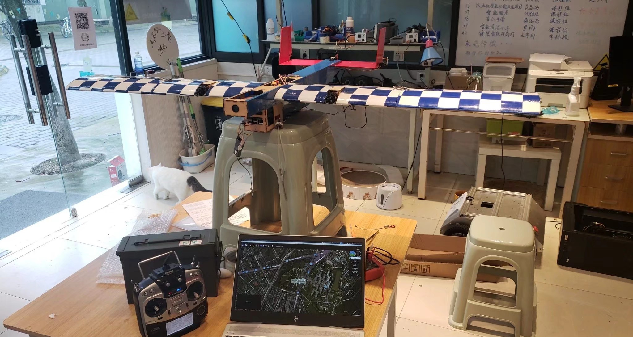
This new PCB design has no actual flight tests as it is still under development. I have done the flight on a multi-rotor and fixed-wings for several times with no PCB but Dupont line connection(sounds crazy). Works fine.
Why I did’t deploy JST-GH connector? Because most of cheap components come with old connector… they are more smaller…
If everything goes well, I’d like to request this to be added into officially supported list, as it should be compatible with any new changes from RPi side and PX4 side. Benefits from the architecture of PX4.
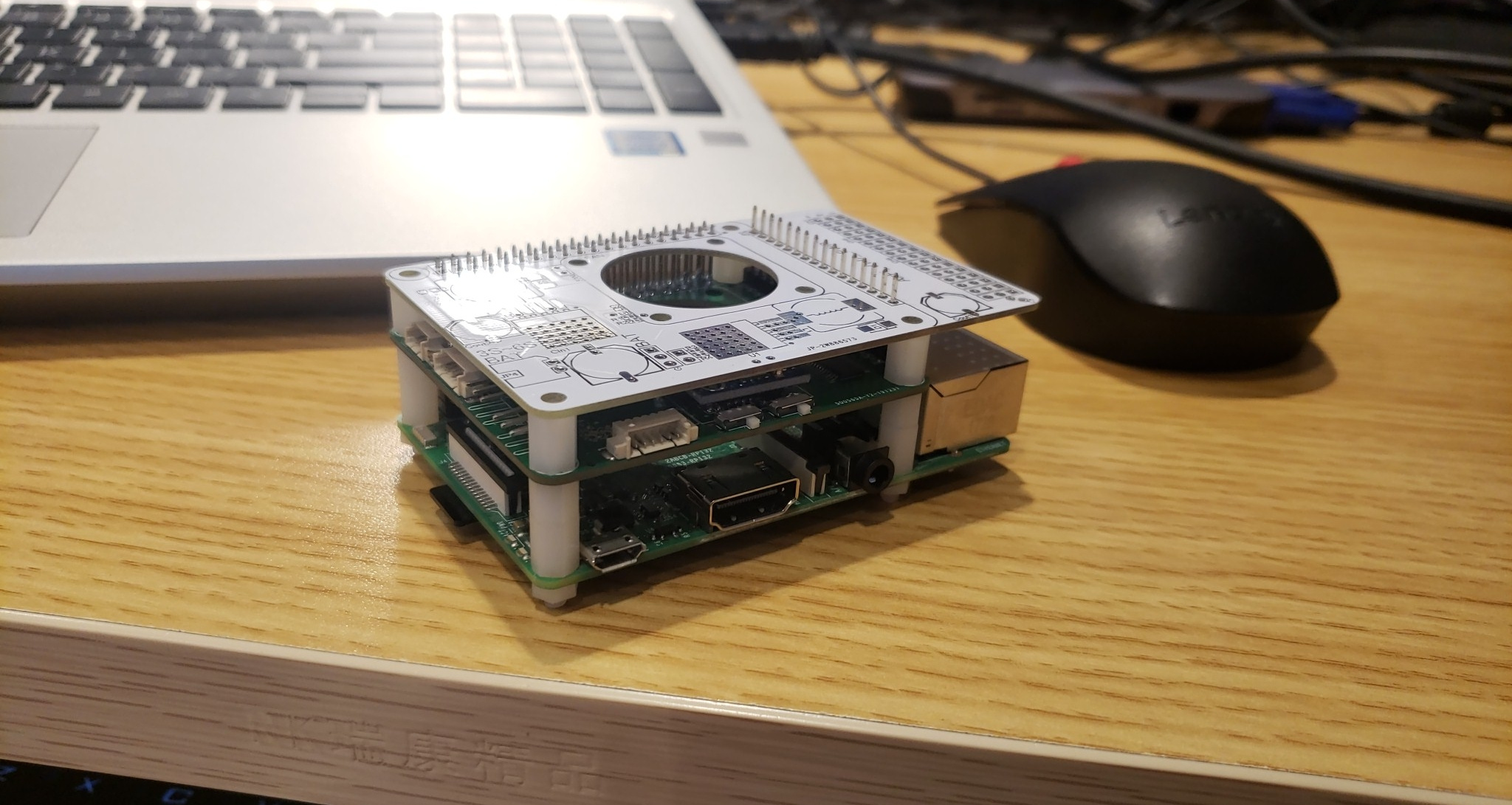
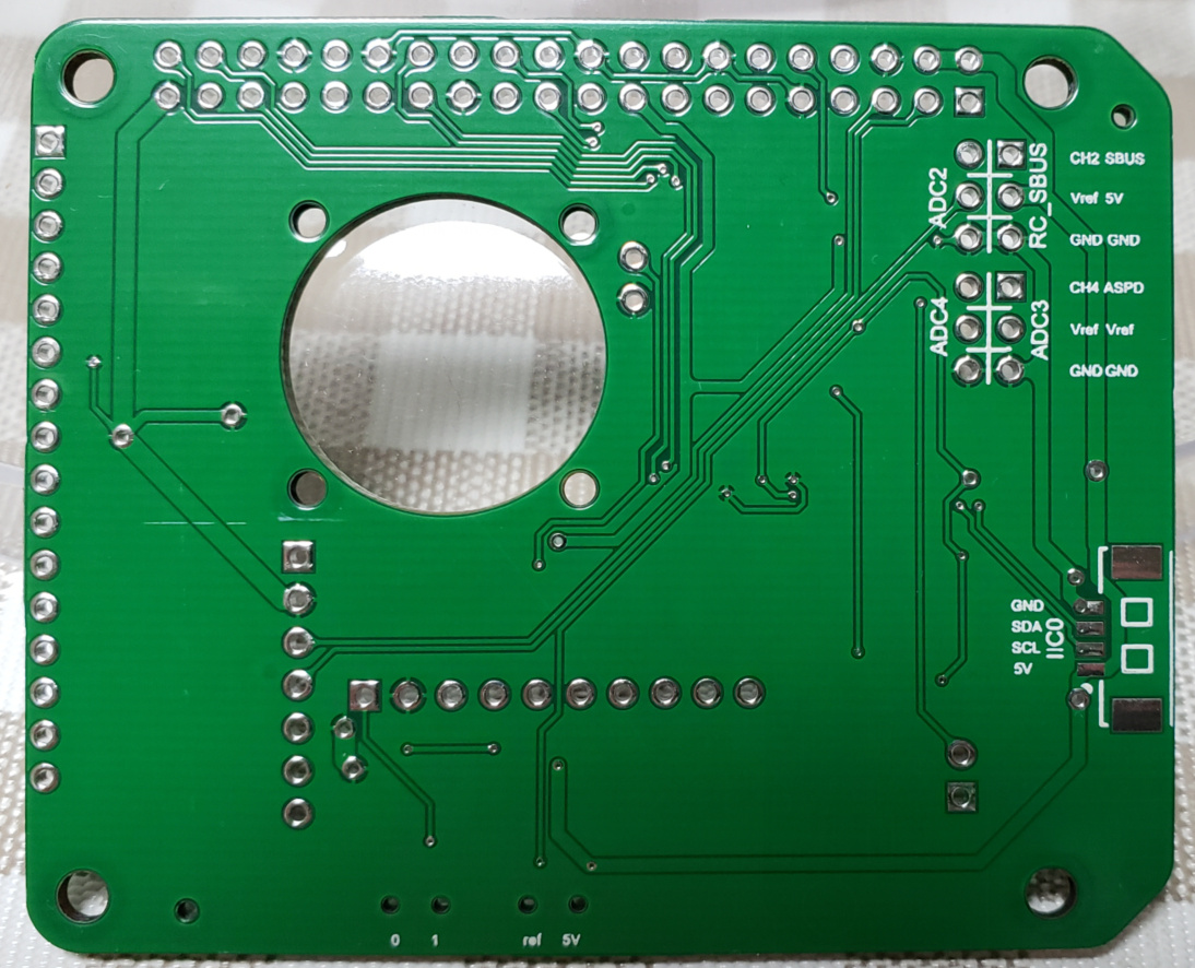
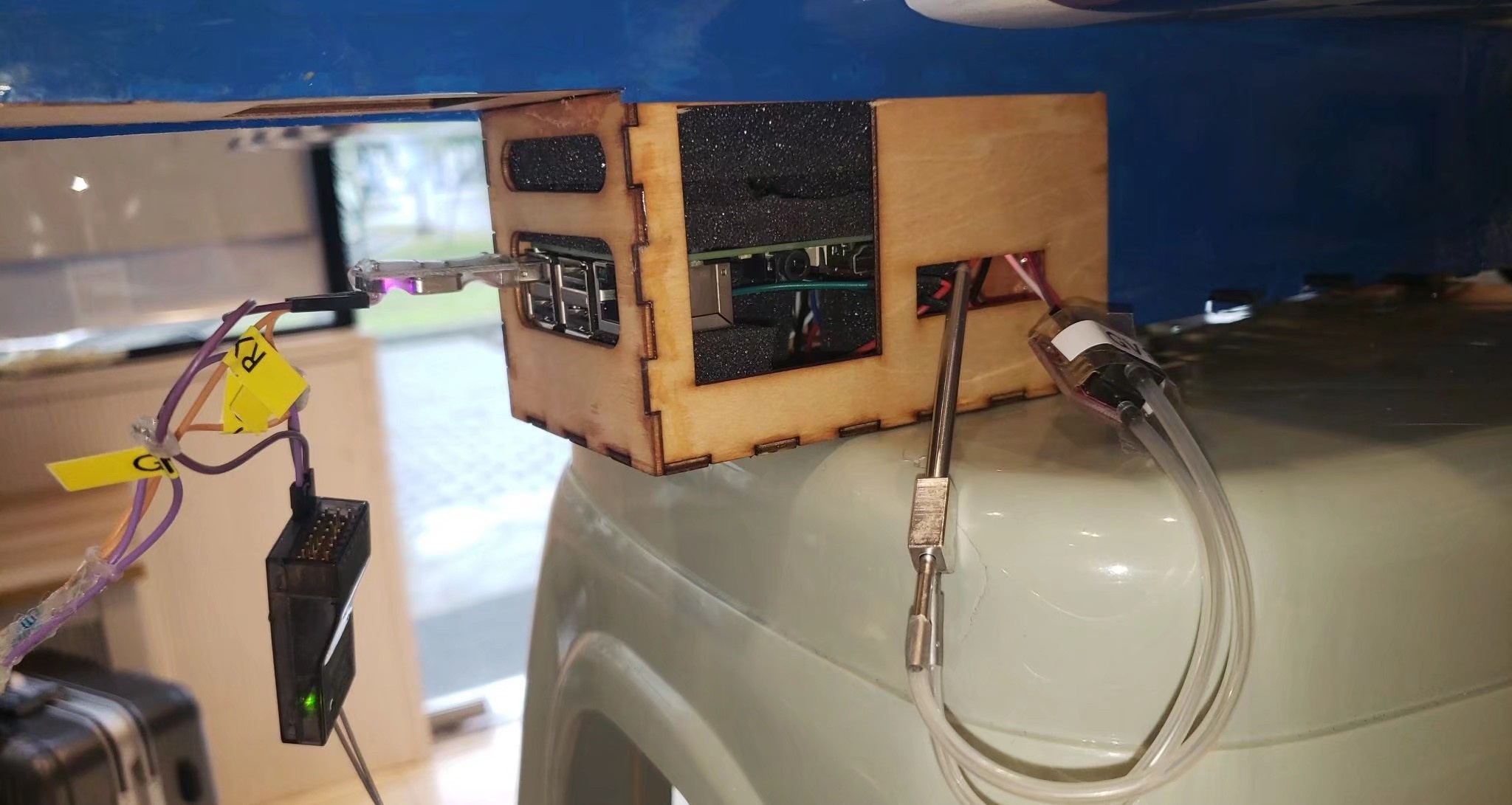
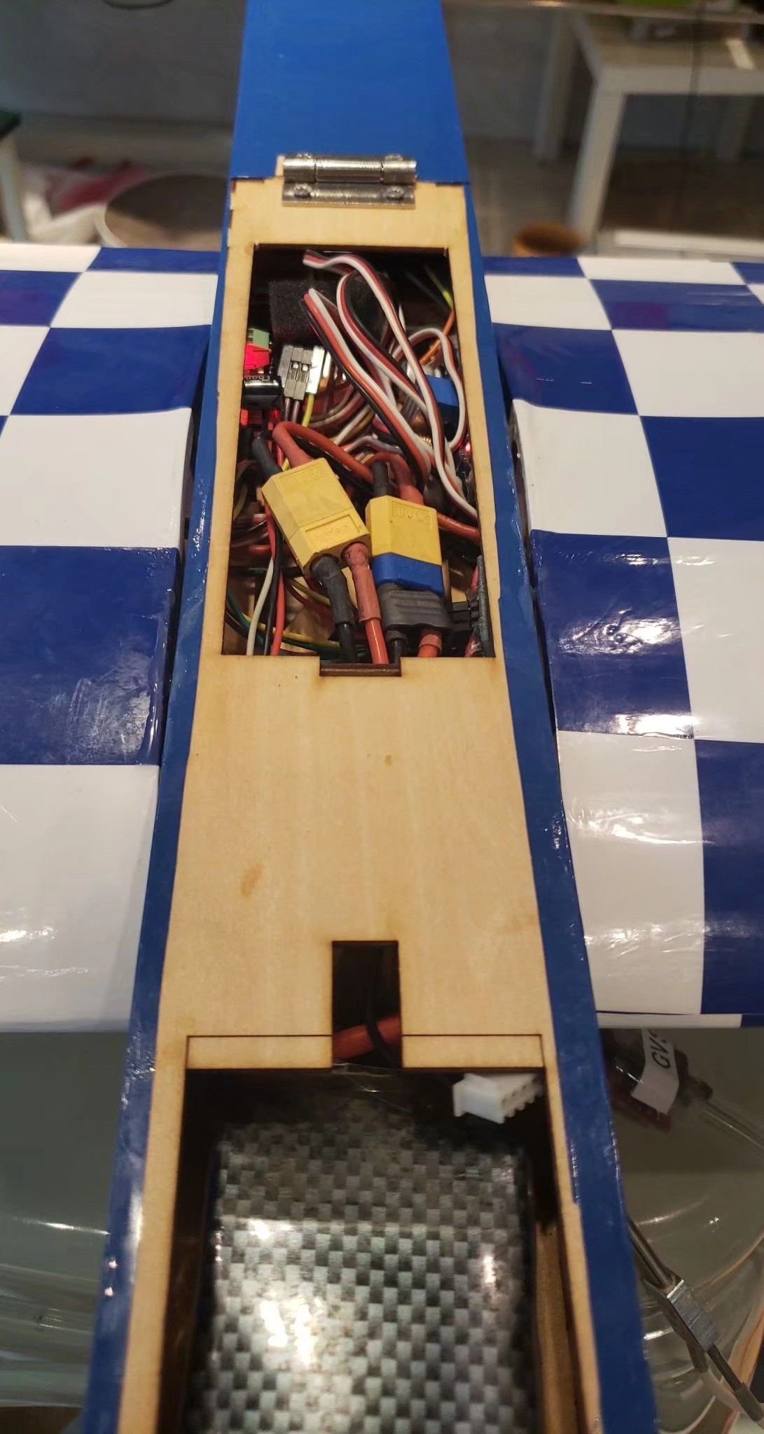
Some recent pictures(still not the latest one, and even not soldered):
I’m a hobbyist in these matters, but do have some experience here I believe. So, I thought, I might share some thoughts which crossed my mind when I saw this.
(I don’t use your pcb design program, so just can look at the pictures you provided)
MPU9250: The mpu9250 is EOL since a while and you can’t even buy it anymore from e.g. mouser etc. While you still can find the modules like you use them, however, eventually even that stock will be depleted. This may affect the longer term success of your design. I guess I would go with a more modern icm, like the icm42605 which is working very well for me (but is just 6DOF)
it seems you have routed wires between the gnd pins on the 40-pin header. That’s not optimal, and in fact it would be better not to do it. Your layout program should allow this.
I understand that you chose the spi1 for the sc16is752, since the dtb is provided by raspberry. However, modifying this dtb for use with the spi0 is easy (even I could do it LOL), and swapping spi1 with spi0, and to put the other stuff on spi1, would result in a much simplified layout: Just look at the locations of the sc16is752 and the MPU, it’s clear that the sc16is752 is closer to spi0 and the mpu closer to spi1 …
It seems you use a simple transistor inverter for the sbus. Using a xor gate would allow a much broader use and larger flexibility. Also, the CMOS xor gates have some very useful signal shaping and level shifting capabilities, which makes them a better choice. 1-gate xor chips in sot23-6 package are available.
Please just don’t use the LM2596. There are soo many soo much better options available.
Your routed wires very often are very close to each other even though the space would be there to separate them easily by some ground plane. Just to give on example, in the pic of the bottom side of the AirPiv1.3, right to the fan hole, there is a thick wire running next to the two serial wires, you easily could have a ground separation here. And similarly the ADC2 wire is running along the serial wire, here too a ground separation would be easily possible, and would probably help getting better adc readings here.
Please don’t take these comments as negative in any way. Given the constraints you mentioned this is really a great project, and I wish you all the best with it.
Thank you very much for your suggestion! Actually I’m just a beginner in this field, no doubt so many defects here…
I’m considering replacing MPU9250 with something like ICM20948 or else, which are already deployed on Pixhawk. Due to limitation of SMD skills, this board may finally just like it is now… Since IMU is not directly mounted on to my PCB so we can change it even after this board is released, just by modifying drivers that are started in the startup script.
I’ll tell my teammate who is responsible for PCB layout about that… Both of us are newbies… I only provide schematics to him.
what I care about most is that I should not introduce any module that is not supported by OFFICIAL. Of course I’d like to improve that dtb to be compatible with different SPI buses, then it is convenient enough to do that.
about inverter, that’s true. I’ll replace it with logic gates if possible(hope I could find one in local market…)
LM2596 works not very well, for sure. I have already considered other replacement.