I’m developing a custom flight controller, based on the FMU-V6c. I’d greatly appreciate your feedback on my schematic, pin assignment, and design to ensure compatibility and reliability.
schematic and other files available at this link
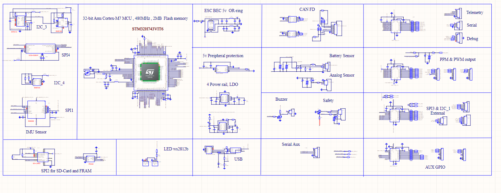
My design uses an STM32H743VIT6 32-bit Arm Cortex-M7 MCU operating at 480MHz with 2MB of Flash memory,
This flight controller board is equipped with several key sensors: an IST8310 magnetometer, a BMI088 accelerometer and gyroscope, an ICM-42688-P inertial measurement unit (IMU), and both BMP388 and BMP390 barometric pressure sensors.
For PX4 parameter management, an FM25V01A-GTR FRAM is used for saving non-volatile data, while a microSD (TF) card handles data logging
The board provides eight PWM outputs for ESCs and six auxiliary GPIOs, each with PWM output capability. All analog input pins are protected by a capacitor filter and a voltage divider with a ratio of 11:1 (using a 10k and 1k resistor). Digital pins connected to external connectors are level-shifted to 5V using a TXS0108ERGYR TTL converter, while internal sensors are connected directly to the specified peripherals.
for power two dual-channel NCV8154MW330330TBG LDOs. used
One LDO is dedicated to powering the MCU and the ICM-42688-P IMU, while the second LDO powers the BMI088 and the remaining sensors. To enable or disable power to the sensor rail, pin PA15 is used as an enable signal. The other three LDO enable pins are tied high for continuous operation. A BLM18PG121SN1D ferrite bead protects the power pin of each internal sensor.