@Abel Correct, the thrust needed to hover is added to the velocity controller so the integral doesn’t need to compensate for the weight of the drone. It is added with a negative sign since thrust_sp is computed in the NED frame (vertical thrust, pointing to the sky is negative in this frame).
which is input θref and θ in the code of pixhwak?.
vehicle_attitude_setpoint_poll();
_thrust_sp = _v_att_sp.thrust;
/* prepare yaw weight from the ratio between roll/pitch and yaw gains */
Vector3f attitude_gain = _attitude_p;
const float roll_pitch_gain = (attitude_gain(0) + attitude_gain(1)) / 2.f;
const float yaw_w = math::constrain(attitude_gain(2) / roll_pitch_gain, 0.f, 1.f);
attitude_gain(2) = roll_pitch_gain;

/* get estimated and desired vehicle attitude */
Quatf q(_v_att.q);
Quatf qd(_v_att_sp.q_d);

/* ensure input quaternions are exactly normalized because acosf(1.00001) == NaN */
q.normalize();
qd.normalize();

/* calculate reduced desired attitude neglecting vehicle's yaw to prioritize roll and pitch */
Vector3f e_z = q.dcm_z();
Vector3f e_z_d = qd.dcm_z();
Quatf qd_red(e_z, e_z_d);

if (abs(qd_red(1)) > (1.f - 1e-5f) || abs(qd_red(2)) > (1.f - 1e-5f)) {
	/* In the infinitesimal corner case where the vehicle and thrust have the completely opposite direction,
	 * full attitude control anyways generates no yaw input and directly takes the combination of
	 * roll and pitch leading to the correct desired yaw. Ignoring this case would still be totally safe and stable. */
	qd_red = qd;

} else {
	/* transform rotation from current to desired thrust vector into a world frame reduced desired attitude */
	qd_red *= q;
}

/* mix full and reduced desired attitude */
Quatf q_mix = qd_red.inversed() * qd;
q_mix *= math::signNoZero(q_mix(0));
/* catch numerical problems with the domain of acosf and asinf */
q_mix(0) = math::constrain(q_mix(0), -1.f, 1.f);
q_mix(3) = math::constrain(q_mix(3), -1.f, 1.f);
qd = qd_red * Quatf(cosf(yaw_w * acosf(q_mix(0))), 0, 0, sinf(yaw_w * asinf(q_mix(3))));

/* quaternion attitude control law, qe is rotation from q to qd */
Quatf qe = q.inversed() * qd;

/* using sin(alpha/2) scaled rotation axis as attitude error (see quaternion definition by axis angle)
 * also taking care of the antipodal unit quaternion ambiguity */
Vector3f eq = 2.f * math::signNoZero(qe(0)) * qe.imag();
Please help me to understand. I am new to this pixhwak and learning it now?..
I am trying to achieve more accurate and stable altitude hold.
Position control looks like it only has proportional gain and does not account for integral errors.
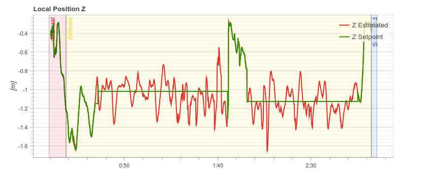
As shown my test below, I am having state error problem when maintaining altitude.
Adding integral terms will help making better position control especially for altitude hold?
Please give me any advice.
Thanks,
@Kyuhyong_You The altitude controller is composed by two cascaded position-velocity loops. The position loop contains only a P controller (as you said) but the velocity loop contains a PID controller which removes steady-state errors. Therefore, the position controller doesn’t need an integrator and tuning the velocity controller should fix your issue.
See: https://dev.px4.io/en/flight_stack/controller_diagrams.html
I’m bit confused now.
Looking at the plot where velocity commanded during altitude hold mode, the drone seem to follow velocity command quite accurate. Isn’t this means the velocity controller is already tuned well?
If that’s the case, shouldn’t the drone also very accurate maintaining certain altitude as well?
FYI, the entire log is here https://review.px4.io/plot_app?log=dca4dfa5-051e-491d-8ab4-c25afe2098af
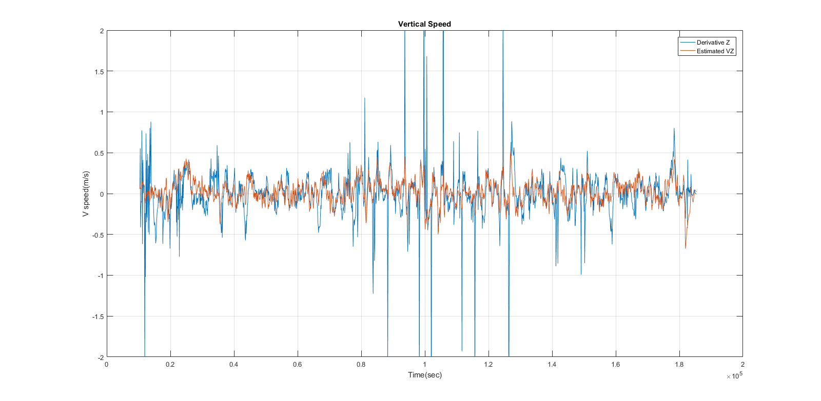
@Kyuhyong_You If the velocity tracking is good, it usually means that the velocity estimation is no correct. Check if the estimated velocity corresponds to the derivative of the position.
Hi @Kyuhyong_You , sorry for the late answer,
The estimated velocity looks to be not good enough. I would recommend you to increase the noise variance of the accelerometer in the EKF.
Please tell me if it solves the issue.
Hi @bresch , Thanks for your comment.
I see some improvements with increasing the EKF2_ACC_NOISE parameter but not completely remove the problem.
Will do more testing tho. 
Indeed you did a really nice job here man. Just saved me a lot of hassle. Thanks a lot.
Hello,
I am modeling the flight controller diagram in simulink and I want to know what is the output of the cascade p-pid loops for attitude and altitude in common flight controllers like pixhawk. Is it moment and force? Or throttle percentage or pwm or anything else?
Because I have considered moments and forces as outputs of my diagrams and as long as my multirotor is heavy and large (with a high mass and moments of inertia) my pid gains in the inner loop has become very high (about 200 - 300).
I want to know what I should consider for the output of my diagrams so that I can use the pid gains which are tuned in simulink, for the real multirotor and pixhawk.
Thanks.
Hi @Asghari936 ,
In PX4, the outputs are normalized values. For a rotor: 1 = maximum speed, 0 = minimum speed
Hi bresch, @bresch
Thanks for your reply👌
So normalized value for roll or pitch moment is the condition in which on rotor is at the maximum speed and the other on the opposite side is at the minimum speed?
For torques, we have -1 (maximum negative) and +1 (maximum positive). So for example, a maximum pitch down demand will be “-1”.
The actual rotor speed will depend on the control allocation gains (mixer).
@bresch
I got it. So what are the default mixer gains? Actually I want to assume a default condition so that I can simulate it in simulink. For example, if the input is just maximum roll (+1) in the hover condition and not anything else like pitch, yaw or throttle, what command would mixer send to motor? Is it to maximize the left motor speed and minimize the right one for + configuration? (And also maximize the two left motor speeds and minimize the right ones for x configuration?)
You can look at the generated control allocation matrices when compiling the code under
build/px4_sitl_default/src/lib/mixer/MultirotorMixer/mixer_multirotor_normalized.generated.h
To generate the motor output, use the following formula:
u = P m
Where u is the normalized motor output vector, P is the control allocation matrix and m is the normalized torques (roll/pitch/yaw) and vertical thrust.
For a quad_plus, the control allocation matrix is straightforward:
static constexpr MultirotorMixer::Rotor _config_quad_plus[] {
	{ -1.000000, -0.000000,  1.000000,  1.000000 },
	{  1.000000, -0.000000,  1.000000,  1.000000 },
	{ -0.000000,  1.000000, -1.000000,  1.000000 },
	{ -0.000000, -1.000000, -1.000000,  1.000000 },
};
And for a quad_x, the gains are slightly lower to get the same roll/pitch/yaw gains (note that 0.707 * 0.707 = 0.5):
static constexpr MultirotorMixer::Rotor _config_quad_x[] {
	{ -0.707107,  0.707107,  1.000000,  1.000000 },
	{  0.707107, -0.707107,  1.000000,  1.000000 },
	{  0.707107,  0.707107, -1.000000,  1.000000 },
	{ -0.707107, -0.707107, -1.000000,  1.000000 },
};
Thanks bresch @bresch. Is this mixer code usually the same for every flight controller that ardupilot supports?
Like other pixhawk versions or old flight controllers like apm that was supported before?
ArduPilot is completely different software. Best to ask about ArduPilot at discuss.ardupilot.org or perhaps for this question in their developers discord (ArduPilot)
Could you please check your messages?