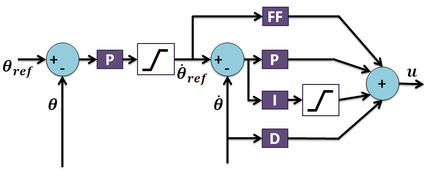
For my master’s project I need to create the Simulink model for the position and attitude controllers of the PX4 firmware, so I can perform some analyses on its performances in simulation. I see that they are very dependents of the flight mode but for the moment I am just looking for a general diagram of the controller structure (Inner/Outer loop P, PID). I have review the mc_att_control_main.cpp and I have identified the following block diagram.
I see that position control use a similar controller but I do not understand yet how it is connected to the attitude controller.
I would appreciate if someone could confirm the identification I have done and suggest documentation about this problem so I can better understand the code.
Hi, you diagram looks pretty good. The feed-forward path is not used for multirotors and it would require a derivative term with it. I think it’s mainly used for helicopter attitude control. Maybe you could use better symbols for the integrator and the derivative, at first I had the saturation confused with an integrator.
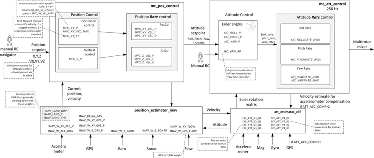
The position controller looks pretty much the same, with an outer position loop feeding the inner velocity loop.
The output of the position controller is an attitude and a thrust setpoint which is the input for the attitude controller.
Hi, I think that the input of the D block should be the error (theta-dot_ref - theta_dot) and not theta-dot directly (same input as inner-loop P and I). Am I wrong ?
I really think that angle rate signal is used for derivative component of PID.
Here there is a section of the mc_att_control_main.cpp code where I believe PID is implemented :
I’ve been digging deep trying to understand how the position and attitude controller is implemented. I’m some how confused. Could you share with me the final control diagram that you’ve got. It will help me to understand the implementation. Thanks a lot.
Hi Abel,
I do not have yet a diagram for position control, but it seems to be very similar to the attitude controller.
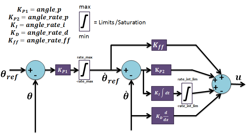
Here is the attitude controller diagram with the corrections suggested before.
Theta is the angle, you just need to replace it by roll, pitch or yaw angle.
Theta dot is the rate of the angle.
For yaw, there should be also a feed forward gain added to the proportional gain for the angle error.
@yun The D is taken directly on the angular rate (filtered gyro measurement) and not on the angular rate error in order to avoid the so called “derivative kick”. For example, imagine what is the output of the derivative term if the reference is a Heaviside step function…
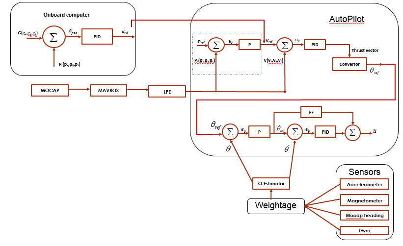
I am trying to expand this controller diagram to include the sensors and their frequencies. Please see the diagram attached and kindly please let me know , how may I improve it more. Specially the LPE estimator, how can I dig into it more?
Very helpful diagram! Where did it come from, or did you make it? I’ve been looking for diagrams to help me understand the attitude control algorithm and haven’t really found anything detailed until now.
There is also MC_YAW_FF parameter that controls how much of user input need to feed forward to yaw rate controller. 0 means very slow control, controller will start to move yaw only when sees yaw position error, 1 means very responsive control, but with some overshot, controller will move yaw immediately, always keeping yaw error near zero.