Thank you very much for your response.
I have another question about the Fixed-Wing Mixer block in the diagram above.
I’m trying to find the equations used in the Mixer block. Would you be able to spell out the equations in the block?
Thank you very much for your help.
I’m looking for the codes for the expression below in a script.
elevator_deflection = trim + pitching_rate_sp * scale
Could you point out the location of the codes?
Thank you very much for your reply.
In the script below, it says “/* add in manual rudder control in manual modes */”.
So, does it also apply to stabilized mode?
I have another question for multicopter stabilized mode in the post below.
If you are familiar with the issue and can answer to my question, that would be much appreciated.
Manual modes are all modes are all modes in which the user interacts with a RC/joystick, so full manual, stabilized, altitude control, position control.
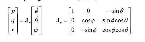
Hello! I am confused that why there is need to add a Jacobian Matrix here? because the phi, thita and ps are Euler angles and their dericatives are attitude rate.
because the phi, thita and ps are Euler angles and their dericatives are attitude rate
Not directly, body rates are not the same as attitude derivatives. That’s only correct for 0 roll and pitch (in which case the Jacobian becomes an identity matrix).
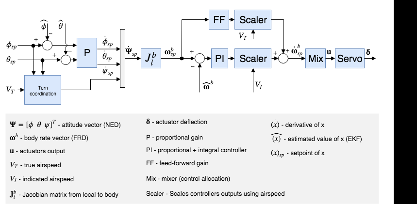
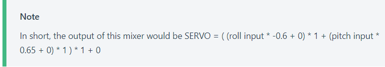
My questions are about the variables that appear in this expression:
I imagine that SERVO will be the input in servo block, so is it the pulse width expressed in ms?
Taking into account the FW Attitude Controller diagram, the mixer input is the derivative of body rate vector, so are the pitch/roll inputs angles or are they angular accelerations?
If u is the pulse width, where could I find how the servo block works to get the angular deflection of control surface?
I imagine that SERVO will be the input in servo block, so is it the pulse width expressed in ms?
SERVO stands for the input to the output driver, which is then mapped to e.g. a PWM.
Taking into account the FW Attitude Controller diagram, the mixer input is the derivative of body
The mixer inputs are the outputs of the rate controller, which tries to bring the rate error to zero. Beyond that I don’t really understand your question, please elaborate.
If u is the pulse width, where could I find how the servo block works to get the angular deflection of control surface?
That is specific to your hardware, you need to set the PWM limits such that it gives the desired deflections at min/max control output. Or even better: adapt the hardware such that you have the full range of 1000 PWM to 2000 PWM for example.