Related topics seem to be old (Modifying px4 multicopter code for 6DOF control) or inappropriate – eg. UUV is underwater I think.
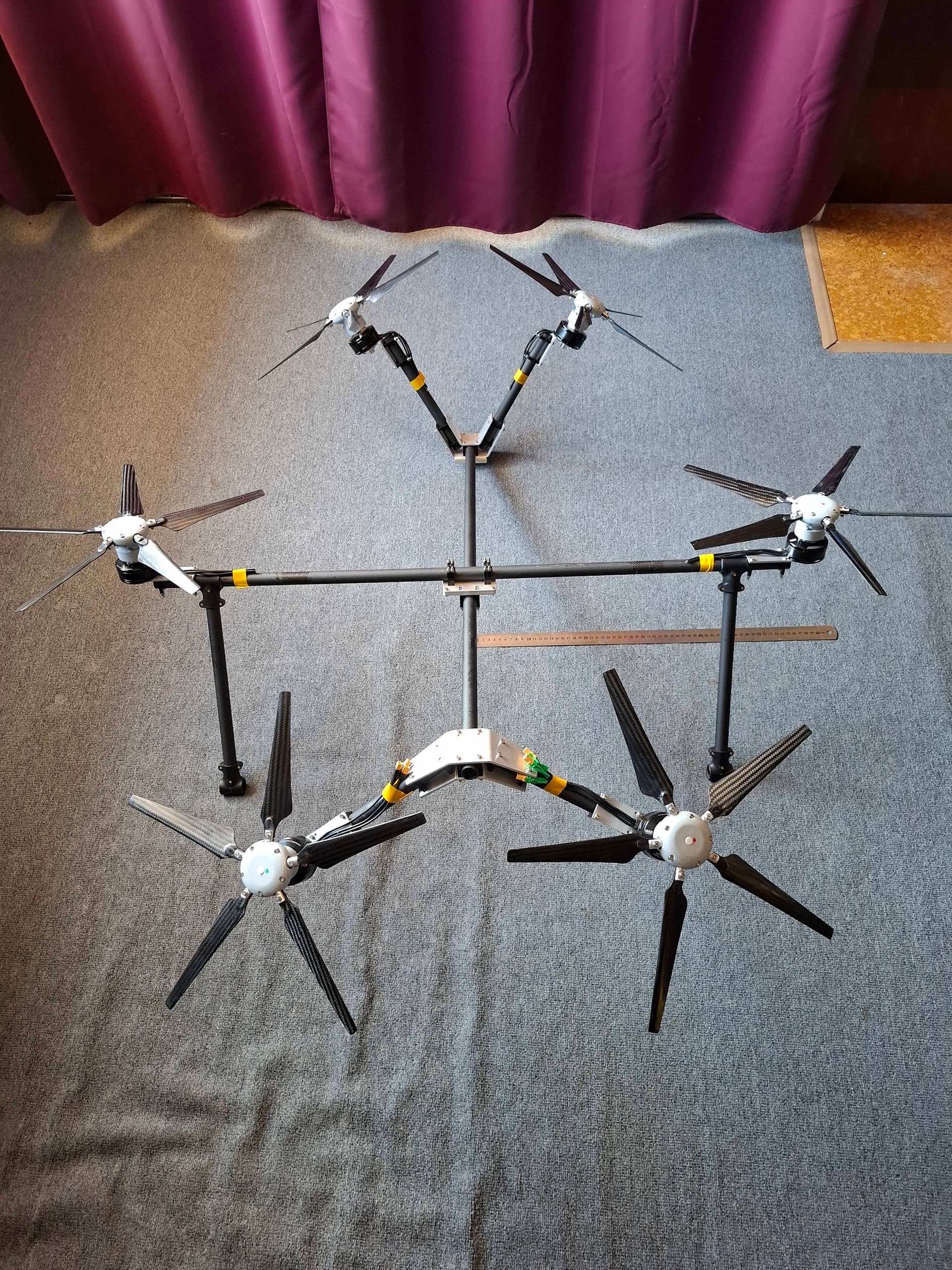
I’ve built a novel 6Dof frame
and so now beginning ( I mean REALLY beginning) to investigate software for flying it.
I do have a linear operator matrix for rotor thrust → net vehicle force and torque, and the inverse operator net vehicle force and torque → matrix for rotor thrust. The matrix is reasonably well conditioned for the pictured configuration.
Ideally I’d like to plug this matrix into PX4 code, or at least adapt the code so I can do that.
But I don’t know where to find all the relevant code in the GitHub repository. Any help would be very much appreciated !!!
A note on my novel 6DoF frame. It has novel collective-pitch 5-bladed rotors. The motivation for 5 blades is to reduce vibration: Off-axis airflow causes blade flap, but the oscillatory forces on 5 rigid blades largely cancel out at the hub. The collective pitch can be adjusted, but primarily is driven by motor torque with an elastic-inertial time-constant of around 4 ms. Much quicker response than waiting for large fixed-pitch blades to spin faster or slower.
You can refer to this page:
1 Like
Thanks very much! Looks like an excellent starting point that I had not discovered!
I can guess what those setup parameters mean, but will try to dig deeper to find out what the code really does with them. Since I know nothing yet, it wont be quick!
Very interesting concept. Do you have any details on the parts used for construction? I have never seen a 5 blade collective pitch hub for a drone before.
Thanks, Iv’e not seen another 5 blade collective pitch hub either. These are my own design. One issue with 5 blades is that all the ones I’ve bought were not uniform. Weights differed by > 1g . So I’ve had to do a lot of re-work to balance the blades. I’ve ordered another batch of (slightly larger) 1865’s, but expect the same problem. Blades often come in matched pairs, but 5 is not divisible by 2 !
Thanks very much! Looks like an excellent starting point that I had not discovered!
I can guess what those setup parameters mean, but will try to dig deeper to find out what the code really does with them. Since I know nothing yet, it wont be quick!
The hubs are a CnC machined design? I can’t imagine that a 3d print would be strong enough. Having flown RC heli many years ago, I find the mechanics of this really interesting. If this is proprietary, I completely understand, but if it is a hobby level thing, I’d love to see how the design is setup. I often thought about machining heli parts (I have a 4 axis machine in my home garage).
The hubs are a mix of CNC parts machined from 6061 aluminium for me by JTC Model Technologies Co, an optional very high precision part machined by them in 316 SS, off-the shelf bearings and bolts, DOWSIL 7091, and UV-resin parts printed by myself. The resin is Monocure 3D “Tensile Resin”. I have found this resin to be both reliable and strong (strength/weight nearly as good as aluminium). I use a long UV exposure and compensate my design for that to get down to 30 um error. That’s not easy on my machine. The rotors have been run up on a test stand many times, with no sign of failure even when the blades were grossly unbalanced.
I probably want to modify the design to make assembly easier and support up to 7 variants with 1 set of basic parts. For example I found it easy to make assembly mistakes if alignment teeth are not divisible by 5.
I think the design would need revision to machine everything. 1 part is actually printed inside another part, on a temporary support structure. The main alloy spine has 2 sets of male spline groves. Could you machine the matching female parts? I imagine you might use spline keys, but then you might remove too much material. There is almost no spare space inside these hubs.
But I certainly envy your 4 axis machine!
I’d have to see the problem to know if it is possible or practical. I’ve machined splines on the 4th axis before, and typically, the female part would be a male version ground into a broach, but there are different ways to accomplish the same task including sending a part out for wire EDM. My CnC is pretty old, but it generally cuts parts with a reasonable degree of accuracy. If a model was fully defined with toolpaths and everything in Fusion 360, I might try to cut it, but otherwise it’s a time thing.
Nice design! You can expect some serious flight endurance if I understand correctly?
Is it a personal challenge or part of a professional development?
Have you already made a test bench with the actuators?
I know a company that could help, in France, so if you’re in the US it could be affordable 
Interesting that you might use broaching or EDM to cut an otherwise difficult CNC part!
I don’t have any toolpaths, JTC did all that for me. And I gave up on Fusion 360. Instead I’ve used FreeCad, which has some deficiencies such as lack of jointed assemblies, but has improved out-of-sight in recent years. I think It would take me an unacceptable amount of time to change that now.
Thanks. The frame is only a test rig for this kind of design, but yes, I think you have noticed that I have considered flight endurance in this symmetric layout. The primary goal is hovering precision, but I might as well provide flight endurance if I can have that too.
The motors have a 13 mm hollow bore to allow pitch adjustment or even servo control from below. But the only versions I have tested are
a) hubs where blade pitch varies with motor torque. Pitch at zero torque can be changed by swapping a part.
b) a hub that does (a) but pitch at zero torque changed by an adjustment screw underneath the motor.
Please let me know of any French company that might possibly help!
I’m in regional Australia. This is a hobby at present, but I think that is only because commercialisation requires a hard-nosed business plan.