I’d like to learn more about the telemetry data link protocol used in SiK radios and related hardware.
From my brief interaction with the radio hardware, I gather it’s a serial connection with mavlink messages serialized to binary and sent duplex over the radio link. System ID in messages determines routing. RADIO_STATUS messages are injected into the stream. Possibly AT interface for configuration/maintenance. Is there anything else I am missing?
It would be great to check out some lower-level docs on the data standard, if they are available.
@auturgy My original post already includes a link to that very same repository when referencing the injected mavlink messages, and I’m interested in the details of the data link protocol, rather than the implementation of the radio firmware itself. These are independent, since SiK is essentially a substitute for a physical serial cable over which telemetry data flows.
Yes and no: whilst SiK can be used as a transparent serial link, mavlink framing is usually enabled, which aligns the radio packets with mavlink packets. You can also adjust the air data rate and duty cycle independently of the serial data rate.
I’m not actually sure what you’re asking, but the wire format is in the mavlink docs. https://mavlink.io/en/guide/serialization.html
What specifically are you interested in? I’ve spent quite some time reverse engineering the source code of SiK radio to understand how it works when writing my GUI config utility. In a nutshell:
SiK radio is not a transparent serial link - it requires MavLink1 or MavLink2 framed data.
SiK radio operates in simplex / half-duplex mode
SiK radio is configured using AT command set. A remote radio (when connected) can also be configured.
SiK firmware exchanges extra signaling data in addition to user data to maintain lock on frequency hopping and inform participant on signal levels.
SiK supports flow control on both serial and air interfaces.
SiK TDM code is very much self-documenting (if you have some background knowledge).
Thank you @auturgy and @j_p for your replies, this helps.
One of the missing pieces for me was the confirmation of mavlink framing, which I had suspected. Perhaps I was naively/silently hoping that some “official” or “internal” documentation on this existed.
More context on what I’m looking at: I’ve been able to successfully generate and send to the FMU my own mavlink OBSTACLE_DISTANCE messages before, but now I’m running into issues reliably reading the telemetry serial data stream using three-wire connection to Raspberry Pi. Using mavlink_frame_char to decode the messages and to find message boundaries I was only able to mostly reliably “see” HEARTBEAT and TIMESYNC messages, most likely because of their short length. I had confirmed it wasn’t a baud rate mismatch, and made sure the serial read is non-canonical. I’m wondering if it was due to some sort of noise, a timing (burstiness) issue which requires more sophisticated buffering, additional envelope information in the byte flow which I was missing, or something else - thus my post.
Have you run into this kind of initial issue with being able to reliably read/parse incoming serial telemetry data from the FMU (on Linux)? Is the three-wire serial connection (no flow control) the issue here?
I have always used USB rather than serial and have/had no problems when running code on Pi/Linux. One thing you could check is that you really use MavLink2. A single MavLink1 message (like a HB) will be enough to force Pixhawk to MavLink1 mode and to ignore OBSTACLE_DISTANCE, which is MavLink2 message.
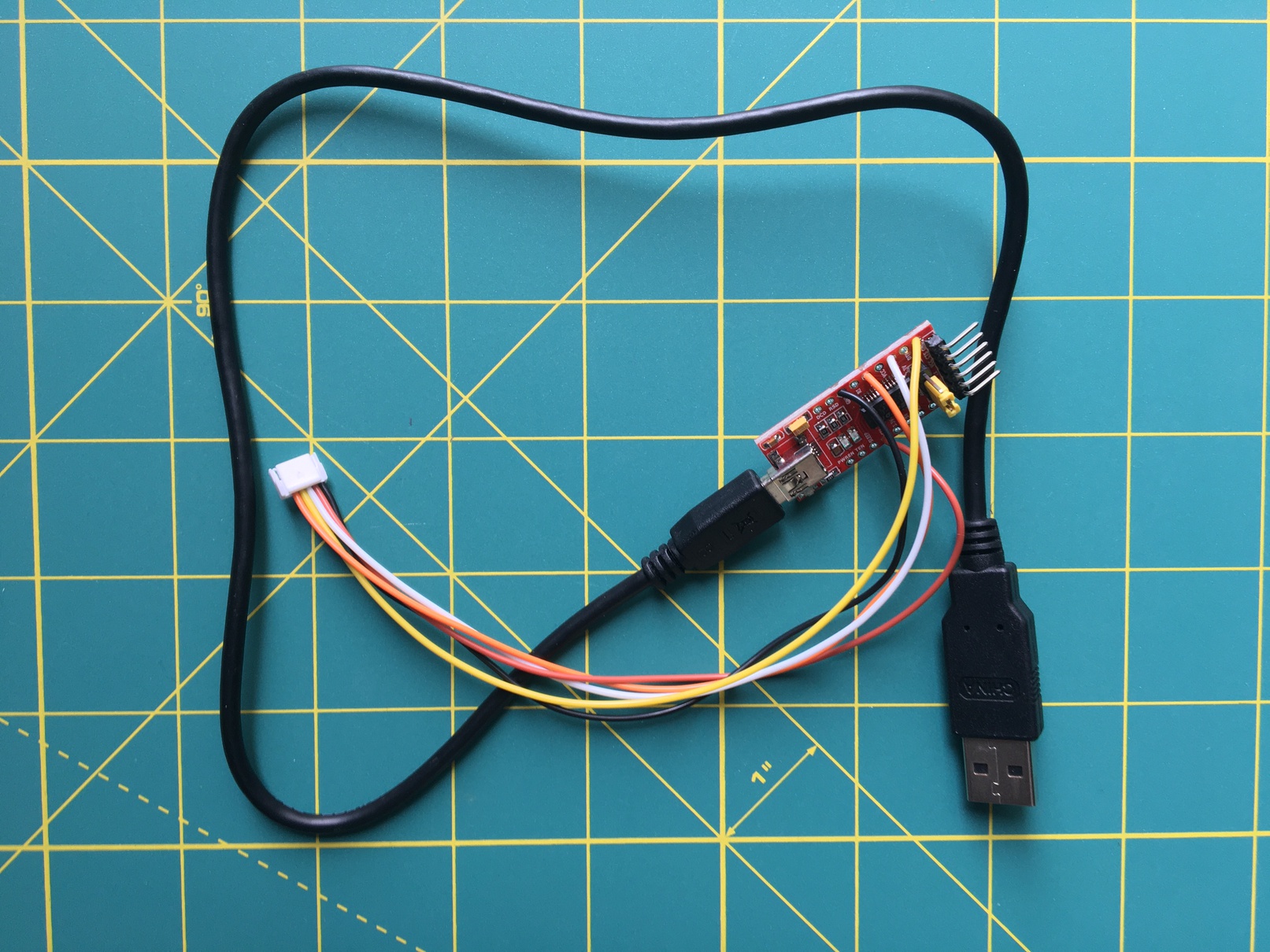
Your comments about flow control earlier and USB made me think to try one of those cheap FT232RL TTL modules I had bought on eBay to wire this and hopefully isolate the issue as part of troubleshooting, before trying to cable/configure RTS/CTS on RPi. I’ll also dig into the SiK firmware code.
It was the lack of flow control with the three-wire UART connection between RPi and Cube that was causing dropped bits and packets. Confirmed working with a homemade connector utilizing the FTDI module; with CTS/RTS the messages are coming through nicely.
In case this helps someone: the additional lesson learned was that the FTDI connector adds the benefit of a much larger buffer (256 bytes RX and 128 bytes TX) vs onboard Raspberry Pi’s UART’s 16 bytes each for RX and TX in RPi 2 & 3 (BCM2836 and BCM2837) and 32 bytes for each RX and TX in RPi 4 (BCM2711) - the larger buffer helps with higher data rates.
Hi guys, anyone knows what is the data size in bytes for any single command like takeoff, land, RTL? If I want to send a landing command only what is the data size of such command?