Dear Friends,
If we compair silicon insulated wire vs regular copper wire than which one is best in the view current carrying capacity with same diameter of both wire.
I am making quadcopter, I observed most wires of moter, ESC and battery uses silicon wire. Protection cover of silicon is good in the view of heat but I am thinking in the view of weight of wire.
I have to reduce weight of copter, that’s why I need such information, please guide.
In RC applications the wire is made of copper, the insulation is often PVC or Silicone.
Silicon (a type of rubber not a semiconductor ) is more flexible than PVC, it has very good thermal and electrical properties.
I have found PVC insulation crack after some use in various weather conditions and vibration exposure.
There are claims that silicone insulated wires are lighter but I’m not sure at the moment, looking at wires used in lipo batteries it seems that they are thinner than you would expect looking at an AWG table.
Silicone insulated wires are easier to solder.
To save waight make sure that wires are only as long as needed, some people put ESCs close to the centre of the frame, this has some advantages but one disadvantage is that there is one long wire per arm more (extra waight).
1 Like
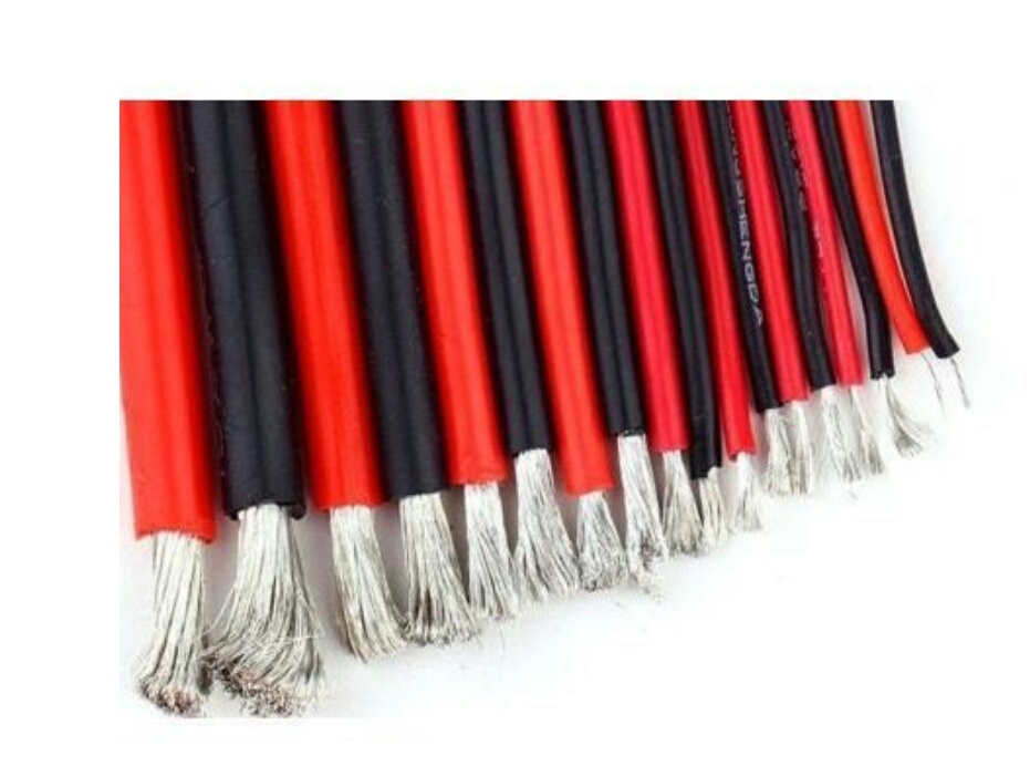
Sir, Thanks for reply, In above imgage , the metal of silicon wire not look like copper, thats look like white color metal
Is there any difference with regular copper wire in the view of current capacity.
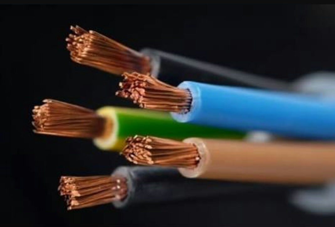
Following image is example of copper wire.
Both images show copper wire the silver coloured one is tin coated, the silver one has very thin strands and it is more flexible then the other one.
Because off the higher temperature rating of the silicone it is possible to push more current through a silicone insulated wire.
Please check this.
http://sparks.gogo.co.nz/silicone-wire-current-capacity.html
https://www.anixter.com/content/dam/Anixter/Wire%20Wisdom/12T0024X00-Anixter-WW-Conductor-Coatings-W&C-EN-US.pdf
1 Like
Sir heartily thanks for your help, you have clear me lot of confusions.
“If any one read this treads , than I have to add something, wire going heat by working current is not good in rc vehicle, because valuable power of battery going loss in heat. If wire is going actually heat and if we think that solve that heat problem by using good insulated same AWG wire like silicon is not good solution, the best way is use large diameter size wire which will not heat.”
Sir please currect me with above my understanding with your valuable practical experience.
Sir if you have possible than please suggest proper AWG (copper wire) for 20 A , 80 A , 100 A , where wire will not heat.
Some chart shows current capacity at maximum level with heat at 60 deg, 75 deg, 90 deg. But we need current capacity of copper wire without increasing temperature of wire.
Please guide
Yes I agree that you want the diameter as large as possible to reduce the resistance and heat but in most cases you have to balance it out.
The wire resistance depends on its cross section area, length and material it is made of.
The weight goes up with the diameter and the length of the wire.
The current draw out of the battery goes up with the weight.
The heat goes up with the current.
Those temperatures in the table are insulation ratings, this does not mean that you will get those temperatures just after plugging it in, it depends on the initial temperature of the wire and ambient air temperature, cooling of the wire, current flowing through the wire and how long it is going to flow for.
There is always some heat generated when current flows through a conductor the questions are how much heat, over what period of time and is it safe?
I do not think there is a ready solution to this problem and I can not just tell you “use 8AWG”.
Can you please tell me where are the 20A, 80A, 100A from?
You can also look at wires in your escs and batteries and use the same AWG, not very scientific but usually works.
1 Like
Sir,
Heartily Thanks to share your valuable knowledge with us.
That is good idea that use same AWG wire of battery and ESC.
Well, I am working on QuadPlane (VTOL), for that first I made plane, worked not bad.
Now working on quad copter, once properly successful in copter than will move on VTOL.
20 A wire for power module to ESC , ESC is 20 A
80 A wire for battery to power module, this require because I have used two batteries each one is 2200 mah. So require small wire for connection. 80 A because 20 A × 4
100 A wire because because Vtol require 5 motors.
You have give me lot of ideas, now i think 80 A or 100 A may not require , I will cut and use some small part of power module wire .
Extra 20 A wire will require, so I will use according to same AWG wire used in ESC power. According to your nice idea.
Sir you are very good person, may Nature bless you all time !
One other thing to consider when you design an electric cirquit like this is do you always use the full current capacity?
Vtol uses 4 motors as a quadcopter and then for a short while 5 during the transition, after the transition it uses only one motor so just adding all up maight be an overkill.
Yes Sir you are right . . . . Thanks
Sir , I found a good web, from that web we can select proper wire with temperature estimate by knowing resistance of wire.
http://circuitcalculator.com/wordpress/2007/09/20/wire-parameter-calculator/
E.g. According to that web, If I get 12 AWG copper wire for 20 A , and if I measure resistance of that wire than we can know temperature of wire, in other language loss of heat.