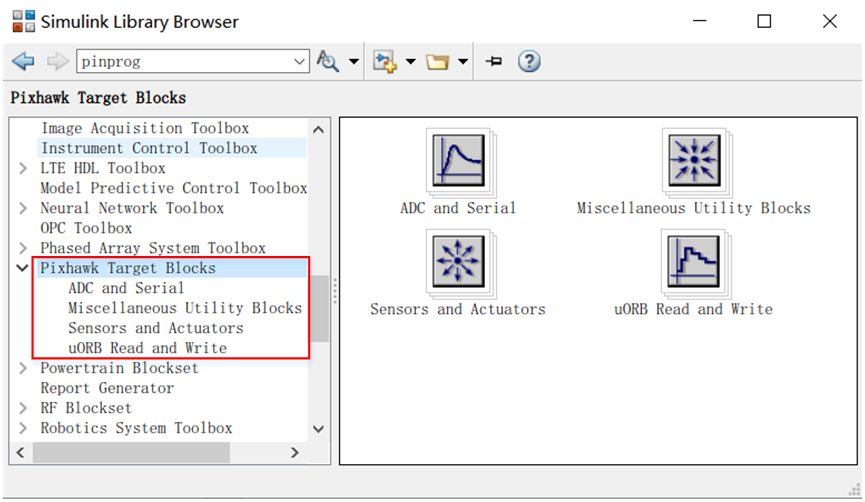
After installing the RflySim platform, you can open the MATLAB/Simulink software and find the Pixhawk Pilot Support Package toolbox in the Simulink Library Browser, as shown in the following image.
For more detailed information, please refer to:
An Introduction to Automatic Code Generation Using RflySim and Simulink。
RflySim:A Toolchain For The Development, Testing, And Evaluation Of An Unmanned Aerial System (UAS) Based On PX4
ADC and Serial Communication Library.
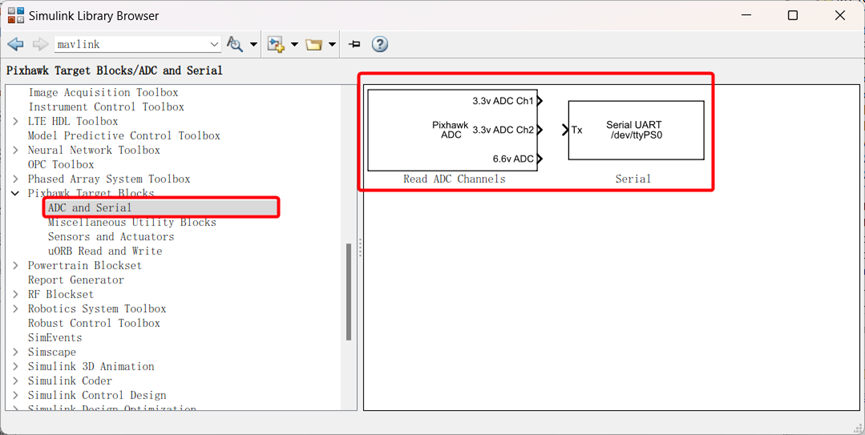
Read ADC Channels
Serial
Allow reading and writing to devices, with the option to specify the device name and read or write preferences.
Miscellaneous Utility Blocks
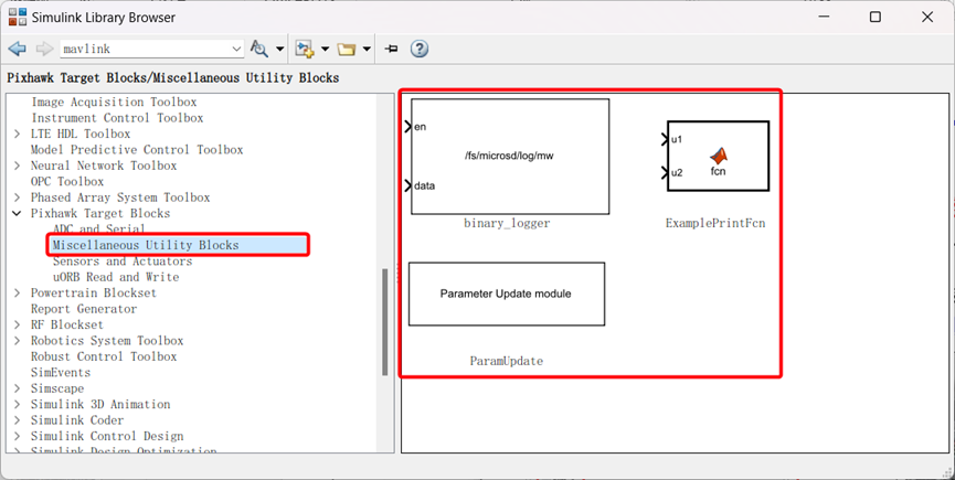
binary_logger
You can record data vectors to a file on an SD card. If caching in memory is enabled, data is written to the file when ‘en’ goes low or when the specified maximum record count is reached. Otherwise, the ‘maximum record count’ is used to indicate when an ‘fflush’ operation to the file should be executed.
ExamplePrintFcn
Show an example module that uses the ‘printf’ function with ‘coder.ceval’.
ParamUpdate
Update custom PX4 software parameters.
Sensors and Actuators
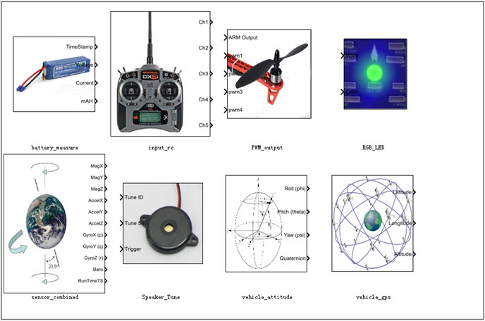
Battery_measure
Through this module, real-time data about the battery can be obtained. It is achieved by subscribing to the uORB topic ‘battery_status,’ so it’s essential to ensure that a power module is connected to the Pixhawk to obtain accurate data during actual operation.
Input_rc — Remote Control Input Module
This module allows you to select the number of channels to receive from the remote control and other information. The meaning of each option can be found by clicking the ‘help’ button in the dialog box or by referring to the official PDF documentation.
PWM_output — Motor PWM Module
Through this module, PWM signals can be sent to the output ports of PX4IO to control motor rotation. You can choose the PWM update rate and input channels.
RGB_LED — LED Module
This module allows you to control the mode and color of LED light flashes. As shown below, the module receives two inputs: ‘Mode’ and ‘Color.’ Available modes and colors can be found by clicking the ‘help’ button in the dialog box.
sensor_combined — Sensor Fusion Module
Through this module, you can obtain available sensor data in the Pixhawk, which can be used for model design. The data that can be acquired includes magnetometer, accelerometer, gyroscope, barometer, and timestamp.
Speaker_Tune — Buzzer Module
This module allows you to control the buzzer to emit specific tones for particular events.
vehicle attitude — Attitude Data Module
This module provides filtered attitude data (Euler angles and quaternions). You can select the desired attitude data for output through checkboxes.
vehicle gps — GPS Data Module
Through this module, you can obtain GPS data from Pixhawk. This is achieved by subscribing to the uORB topic ‘vehicle_gps,’ so it’s important to ensure that a GPS module is connected to the Pixhawk to obtain accurate data during actual operation."
uORB Read and Write—uORB Message Reading and Writing Library
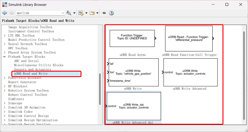
uORB Read Async
Obtaining Data Related to uORB Topics
uORB Read Function-Call Trigger — uORB Message Reading Callback Trigger Module
This block operates in two modes. Mode 1: Reading uORB data, in which the block uses the uORB_CHECK() call to retrieve data and writes it into a structure. This structure is accessed as a bus object. The buttons below allow the creation of bus objects for any uORB message, provided that the message is specified in .msg format. The header file is added to the generated code in C:\px4\Firmware\src\modules\uORB\topics. Mode 2: Asynchronous task, in which the block generates a data-driven thread. When uORB messages for the specified topics arrive, the thread continues execution and runs the associated function call subsystem.
uORB Write — uORB Message Data Publishing Interface Module
This interface allows users to publish specified values or structures to uORB topics.
uORB Write Advanced — Advanced uORB Message Data Publishing Interface Module
This interface permits users to have more flexible control over the data they publish. Using the uORB Write Advanced interface in Simulink enables more complex and precise message publishing. You can choose the message file to write to and specify a message ID. Additionally, advanced options such as message priority and queue size can be set.
uORB Write Advanced_dai
Advanced uORB Message Data Publishing Interface Module with Custom uORB MsgID Functionality.
For more detailed information, please visit https://doc.rflysim.com . The basic and advanced trial versions of RflySim can be obtained by providing your email address through the download link at https://rflysim.com/download . For the full-featured complete version, please inquire at service@rflysim.com .