Hi everyone,
I’m currently working on an Autonomous Surface Vehicle (ASV) project for a university competition, and I would love to get some expert feedback on my wiring diagram and power distribution strategy before I start crimping and soldering.
Our Core Hardware:
-
Flight Controller: Pixhawk 6C
-
Power Module/PDB: Holybro PM07
-
Propulsion: 4x Blue Robotics T200 Thrusters + Basic ESCs (Skid steering setup)
-
Companion Computer: Seeed reComputer J3011 with Jetson Orin Nano (running ROS 2)
-
Battery: 4S 14.8V 5000mAh 60C
Project Context: Our competition has a strict speed limit of 5 knots. To comply with this and protect the hardware, we are placing inline 15A fuses between the PM07 power pads and the ESCs to physically cap the max current draw (also limited in software with MOT_THR_MAX).
I have two main areas where I’d love your input:
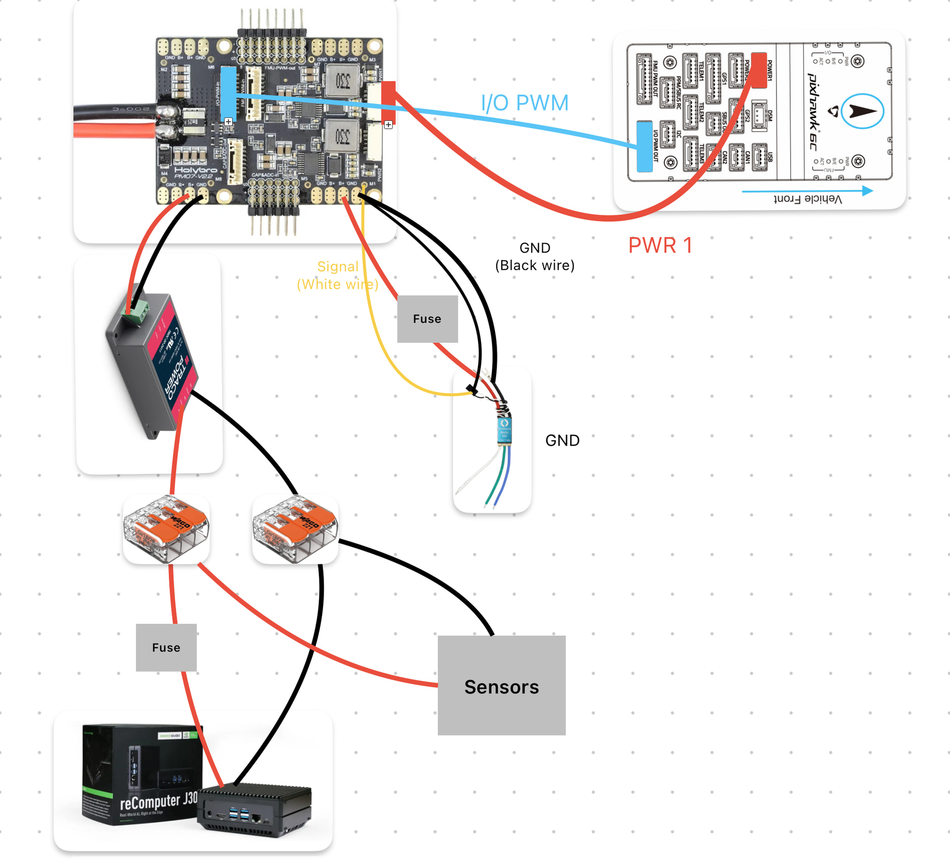
1. PWM Signal Routing Since we are using standard motor ESCs (no servos) and rely on hardware failsafes, I interpreted the documentation and routed the signals as follows:
-
Pixhawk
I/O PWM OUT→ PM07I/O-PWM-in(via the 10-pin ribbon cable). -
ESC signal wires (White/Yellow) → PM07 PWM
Mxpins. -
ESC signal ground (Black) → PM07 PWM
GNDpins (to prevent ground loops). -
FMU PWM OUTis left disconnected.
Does this implementation look solid according to ArduRover/PX4 standards?
2. Powering the Companion Computer via PM07 Motor Pads To power our Jetson Orin Nano and some sensors, we are using an industrial Traco Power 12V DC-DC converter. Since the M1-M4 pads on the PM07 are taken by our thrusters, my plan is to solder the converter’s input (protected by its own inline 10A fuse) directly to the unused M8 B+and GND pads on the PM07.
-
Is this a reliable practice in the ArduPilot/PX4 community?
-
My assumption is that M1-M8 share the same copper planes after the shunt resistor, meaning the PM07 will correctly measure the total system current (thrusters + companion computer). Are there any electrical noise or hardware concerns I should be aware of when pulling logic power from these ESC pads alongside the thrusters?
Thanks in advance for your time and expertise!