Problem with the formula for quaternion rotation in PX4

I was studying PX4 and quaternions, and I learned that quaternions can represent the rotation of vectors and the rotation of the coordinate system.

For the case of theorem of Quaternion - rotation of a vector: given a vector p and a quaternion q,then the vector p rotated by quaternion q can be expressed as pā€™=qpq^-1.

For the case of theorem of Quaternion- Rotation of a coordinate system: given a vector p in the coordinate system XYZ,the XYZ coordiniate system is rotated by a quaternion q to Xā€™Yā€™Zā€™,and vector p expressed in the Xā€™Yā€™Zā€™ coordinate system pā€™ is expressed as pā€™=q^-1pq.

I can ensure that these two formulas should be correct, but when I looked at the quaternion.hpp code of PX4, I found that the formulas in PX4 were different from my understanding. When using quaternions to represent the rotation of the coordinate system, the second formula should be used, but PX4 uses the first one, pā€™=qpq^-1.

Here is the code in PX4

 * In order to rotate a vector in frame b (v_b) to frame n by a righthand 
 * rotation defined by the quaternion q_nb (from frame b to n)
 * one can use the following operation:
 * v_n = q_nb * [0;v_b] * q_nb^(-1)

I think the formula here should be v_n = q_nb^(-1) * [0;v_b] * q_nb

	/**
	 * Rotates vector v_1 in frame 1 to vector v_2 in frame 2
	 * using the rotation quaternion q_21
	 * describing the rotation from frame 1 to 2
	 * v_2 = q_21 * v_1 * q_21^-1
	 *
	 * @param vec vector to rotate in frame 1 (typically body frame)
	 * @return rotated vector in frame 2 (typically reference frame)
	 */
	Vector3<Type> conjugate(const Vector3<Type> &vec) const
	{
		const Quaternion &q = *this;
		Quaternion v(Type(0), vec(0), vec(1), vec(2));
		Quaternion res = q * v * q.inversed();
		return Vector3<Type>(res(1), res(2), res(3));
	}

The code is located in src\lib\matrix\matrix\Quaternion.hpp

I donā€™t know if thereā€™s something wrong with my understanding, but obviously these two formulas cannot be mixed. So I came to ask for any help because it is very important for my further research!

Let me tag @MaEtUgR and @bresch to answer that one.

Hi zhihao,

Operating under the assumption that the quaternion q_nb transforms a vector expressed in the ā€œbā€ reference frame coordinates to a vector expressed in ā€œnā€ reference frame coordinates, the following equation will translate the SAME vector from ā€œbā€ coordinates to ā€œnā€ coordinates:

[0;v_n] = q_nb * [0;v_b] * q_nb^(-1)

Now letā€™s look at what happens when we move the quaternions to the Left-Hand side of the equation:

[0;v_n] = q_nb * [0;v_b] * q_nb^(-1) ā†’
q_nb^(-1) * [0;v_n] * (q_nb^(-1))^(-1) = [0;v_b] ā†’
q_nb^(-1) * [0;v_n] * q_nb = [0;v_b]

This is the same equation, but now weā€™re using the quaternion q_nb to transform the vector [0;v_n] from ā€œnā€ reference frame to ā€œbā€ reference frame. This illustrates how both equations you described are applicable, but whatā€™s more important is understanding what basis transformation the quaternion is applying. Hope this helps!

Hiļ¼@rmselvan

Thank you for your reply and patience. As I am not a native English speaker, I will do my best to express myself clearly

I can understand the two equations and transformations you provided. But what troubles me is that formula ļ¼š[0;v_n] = q_nb * [0;v_b] * q_nb^(-1)

in my understandingļ¼Œshould be ļ¼š[0;v_n] = q_nb^(-1) * [0;v_b] * q_nb

So I tried my best to make sure that the quaternions used in PX4 were the same as what I understood : in my understanding, q_ nb represents the transformation of coordinate frame b to coordinate frame n, which means that if coordinate frame b , rotates around an axis u, expressed in frame b, 2Īø Angle, will obtain the coordinate frame n,.Then this quaternion q should be (cosĪøļ¼Œ sinĪø*u)

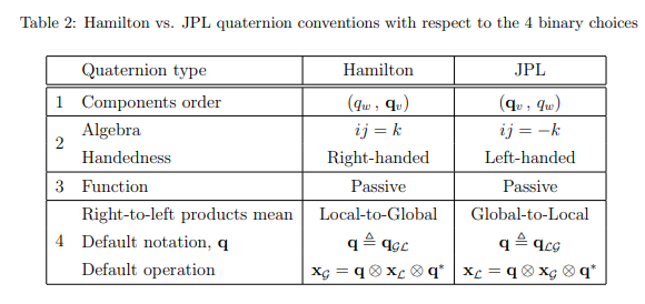
In addition, the Hamilton convention and right-hand rule should be followed , and both of them are declared in PX4.

Based on a simple test I conducted yesterday, I used a fixed wing aircraft ,recorded attitude and flight control quaternion data, and conducted verification calculations. My conclusion is that the quaternion recorded in the topic vehicle_attitudeļ¼Œthough the note said

Float32 [4] q # Quaternion rotation from the FRD body frame to the NED earth frame

But in fact, this q represents the transformation from the NED frame to the FRD frame, and the operation defined in quaternion.cpp is also inverse, so the effect is somewhatļ¼Œ Two negatives make a positive

Can you provide more information about the formulaļ¼Œ[0;v_n] = q_nb * [0;v_b] * q_nb^(-1)ļ¼Œ for expressing the same vector before and after rotating two coordinate frames? Although this may sound a bit offensive, based on the information I have found, it seems that there is indeed a problem with this formula

Thank you very much for your replyļ¼

Hi zhihao,

I appreciate your response! It appears thereā€™s a disrepancy in our understandings of the reference frame order ā€œnbā€ in q_nb.

Iā€™ve done some investigation into mc_att_control AttitudeControl.cpp and my understanding was a little different. To parallel your wording with my understanding:

The quaternion ā€œq_nb represents the transformation of coordinate frame b to coordinate frame n, which means that if coordinate frame b, rotates about an axis u, (i donā€™t think the frame of rotation axis u is too relevant because the coordinates should be consistent in frame n and b), -2theta angle, will obtain the coordinate frame nā€. See my understanding was that the 2theta angle becomes a negative 2theta angle, and this is why I have been comfortable using the equation:

[0; v_n] = q_nb * [0;v_b] * q_nb^(-1)

The reason Iā€™ve used the -2theta angle is because q_nb appeared to me to act like a Direction-Cosine Matrix and not a Rotation matrix. If I translate q_nb to its corresponding direction-cosine matrix (letā€™s call it C_nb), then:

[0;v_n] = q_nb * [0;v_b] * q_nb^(-1) is equivalent to
{v_n} = C_nb *{v_b}

where v_n and v_b are the same vector expressed in reference frame coordinates of n and b respectively. If it were the other way around as you have independently determined, I think it would instead have looked like:

[0;v_b] = q_nb * [0;v_n] * q_nb^(-1) is equivalent to
{v_b} = C_nb * {v_n}

I have previously tried testing the DCM(quaternion q) constructor and the quaternion multiplication functions in parallel and was able to re-create the expected result, but Iā€™d have to dig up the matlab scripts I used to remember what I did.

Regardless, there definitely seems to be some inconsistency between both our understandings of how the PX4 is representing its quaternions, and I am in a similar position where understanding this discrepancy would be immensely helpful to me in the future. Is there anyone else who can clarify the correct interpretation?

Hiļ¼Œ@rmselvan,
If q represents a rotation of -2theta angle rather than 2theta, then the annotations and formulas in PX4ā€™s code would correct, although I still donā€™t understand what convention this is.
Your words makes me realize that I may have been confusing the direction cosine matrix-dcm and rotation matrix. Actually I did not seriously distinguish them.
Maybe you can go take a look at the attitude_ estimator_ q_ main.cpp, which shows how the initial value of quaternion is created through a DCM matrixļ¼ˆor rotaion matrix? Iā€™m really confusedļ¼‰, I think this may be valuable for solving our problem.

bool
AttitudeEstimatorQ::init_attq()
{
	// Rotation matrix can be easily constructed from acceleration and mag field vectors
	// 'k' is Earth Z axis (Down) unit vector in body frame
	Vector3f k = -_accel;
	k.normalize();

	// 'i' is Earth X axis (North) unit vector in body frame, orthogonal with 'k'
	Vector3f i = (_mag - k * (_mag * k));
	i.normalize();

	// 'j' is Earth Y axis (East) unit vector in body frame, orthogonal with 'k' and 'i'
	Vector3f j = k % i;

	// Fill rotation matrix
	Dcmf R;
	R.row(0) = i;
	R.row(1) = j;
	R.row(2) = k;

	// Convert to quaternion
	_q = R;

I should be studying this issue tomorrow at daytime.
Thanks for your helpļ¼

Hi zhihao,

This is the perfect place in the code to look, thank you for pointing it out. I am not fluent in C++ or PX4, so take this with a grain of salt, but if the vectors i, j, and k are respectively the Earth X-axis (North) unit vector, the Earth Y-axis (East), and the Earth Z-axis (Down) vectors as seen in the BODY-FIXED reference frame, then my understanding is that the matrix R is a Direction-Cosine Matrix that transforms a vector {v_b} expressed in the body frame coordinates to {v_n} in the NED frame coordinates:

{v_n} = R * {v_b}

The reason I think this is true is because of the construction of R:

R = [iā€™; jā€™; kā€™] = [i, j, k]ā€™ ā€”> here I am using MATLAB notation for matrices/arrays. ( apostrophe indicates a transpose)

The matrix Rā€™ = [i,j,k] would transform {v_n} into {v_b}. This makes sense because the vectors i, j, and k represent the north, east, and down directions as seen from the body-fixed reference frames. Therefore, the transpose of this matrix (Rā€™)ā€™ == R would transform {v_b} into {v_n} as allowed by the rules of Direction-Cosine matrices. So I am thinking that q indeed uses the -2theta as per your definition of quaternion multiplication.

However, there are a couple things I have not been able to find yet.

  1. I could not find the assignment operator overloading required for the code ā€œ_q = R;ā€ā€¦ this would really help us with checking q

  2. I donā€™t know what the operator * is doing in this code:
    Vector3f i = (_mag - k * (_mag * k));
    I just assumed this line was finding North vector in body frame as expressed in the comment above it.

I would also like to clarify my definition of Direction-Cosine Matrix versus Rotation Matrix just to ensure weā€™re on the same page. A Direction-Cosine Matrix re-expresses the same vector in a different basis/coordinate-system. A rotation matrix actively rotates a vector but preserves the basis/coordinate-system. Really the only distinguishing feature between the two is how I interpret what they do. In essence, they both have exactly the same properties/behavior. I am consistently only using DCMs when I discuss the matrices.

Sorry this got quite long. Hope that this makes sense and can help take us further. Thanks for your insight into this issue.

Hi @rmselvan ,
I am still researching direction-cosine-matrix and rotation matrix, and I may need some time to clarify my thoughts.
For your first question, How q=R is executed, I can provide you with information.
In fact, you only need to look at two files in PX4,
attitude_estimator_q_main.cpp is about initializing attitude quaternions and how to update them during flight control running
attitude_estimator_q_main.cpp

Quaternion.hpp defined operations functions and constructor functions for quaternions
Quaternion.hpp

here is the constructor function

/**
	 * Constructor from dcm
	 *
	 * Instance is initialized from a dcm representing coordinate transformation
	 * from frame 2 to frame 1.
	 *
	 * @param dcm dcm to set quaternion to
	 */
	Quaternion(const Dcm<Type> &R)
	{
		Quaternion &q = *this;
		Type t = R.trace();

		if (t > Type(0)) {
			t = sqrt(Type(1) + t);
			q(0) = Type(0.5) * t;
			t = Type(0.5) / t;
			q(1) = (R(2, 1) - R(1, 2)) * t;
			q(2) = (R(0, 2) - R(2, 0)) * t;
			q(3) = (R(1, 0) - R(0, 1)) * t;

		} else if (R(0, 0) > R(1, 1) && R(0, 0) > R(2, 2)) {
			t = sqrt(Type(1) + R(0, 0) - R(1, 1) - R(2, 2));
			q(1) = Type(0.5) * t;
			t = Type(0.5) / t;
			q(0) = (R(2, 1) - R(1, 2)) * t;
			q(2) = (R(1, 0) + R(0, 1)) * t;
			q(3) = (R(0, 2) + R(2, 0)) * t;

		} else if (R(1, 1) > R(2, 2)) {
			t = sqrt(Type(1) - R(0, 0) + R(1, 1) - R(2, 2));
			q(2) = Type(0.5) * t;
			t = Type(0.5) / t;
			q(0) = (R(0, 2) - R(2, 0)) * t;
			q(1) = (R(1, 0) + R(0, 1)) * t;
			q(3) = (R(2, 1) + R(1, 2)) * t;

		} else {
			t = sqrt(Type(1) - R(0, 0) - R(1, 1) + R(2, 2));
			q(3) = Type(0.5) * t;
			t = Type(0.5) / t;
			q(0) = (R(1, 0) - R(0, 1)) * t;
			q(1) = (R(0, 2) + R(2, 0)) * t;
			q(2) = (R(2, 1) + R(1, 2)) * t;
		}
	}

For the second question, I think your assumption is correct. I have read the explanation on a Chinese forum and it is indeed the projection of the north component in the body coordinate frame, but the calculation process is quite complex
I think your understanding is ahead of mine, I hope it can help!

Hi zhihao,

Thank you for the constructor function! I have looked into it a little more, and I am still thinking that the quaternion is constructed like a DCM rather than a rotation (as per the definition Iā€™d written earlier).

I would like to say that I believe your interpretation from the beginning was correct. The convention you were using would state the following for a coordinate transformation from body axes to NED axes:

[0;v_n] = q_bn^(-1) * [0;v_b] * q_bn ------ (equation 1)

But it just turns out that the convention PX4 is using is q_nb as its quaternion (q_nb^(-1) = q_bn).

So if I take equation 1 and use substitute in q_nb^(-1) for q_bn, I get:

[0;v_n] = (q_nb^(-1))^(-1) * [0;v_b] * q_nb^(-1) ----->
[0;v_n] = q_nb * [0;v_b] * q_nb^(-1) ------ (equation 2)

Which is why they are using equation 2 instead of equation 1. Does this seem to help answer your original question?

Hiļ¼Œrmselvan,
Thank you for your effortsļ¼ I have some doubts about your ļ¼ˆequation 1ļ¼‰.
Firstlyļ¼Œwe and PX4 both believe that q_nb refers to the quaternion of rotation from the b frame to n frameļ¼Œn to b.
The formula I gave at the beginning was [0;v_n] = q_nb^(-1) * [0;v_b] * q_nb, but my understanding is based on a standpoint that the angle of rotation is 2Īø under the right-hand convention.
If the rotation angle is right-handed -2Īø, as you said before.Though q_nb is still written as q_nbļ¼ˆIn fact, the q defined by PX4 here and the q I understand are conjugate to each otherļ¼‰, the formula will become [0;v_n] = q_nb * [0;v_b] * q_nb^(-1), which is used by PX4.
I think it is the direction of the rotation angle of the quaternion defined here that causes this problem.
I hope I have expressed my meaning clearlyļ¼Œdoes your equation 1 is based on the standpoint that, the rotation angle for constructing quaternions is - 2*theta?

Hi zhihao,

Just to clarify, my understanding is that q_nb is the equivalent of a ROTATION matrix that will rotate a vector {v_n} such that it is actively rotated to become new vector in n-frame {vnew_n}. {vnew_n} is {v_n} rotated by +theta about the rotation axis between from n to b. This uses your vector rotation equation:

{0;vnew_n} = q_nb * {0;v_n} * q_nb^(-1)

When q_nb is used as a Direction-Cosine Matrix, it takes the vector {v_b} and represents that same vector in the n-frame {v_n} when using the same equation.

{0;v_n} = q_nb * {0;v_b} * q_nb^(-1)

The axis-angle to quaternion conversion uses +2theta by my equation:
{0;v_n} = q_nb * {0;v_b} * q_nb^(-1)
The axis-angle to quaternion conversion uses -2theta by your equation:
{0;v_n} = q_nb^(-1) * {0;v_b} * q_nb

but I am sorry I see now that saying -2theta may have just increased confusion further. I want to ask you one further question that may aid us. What is the formula you are using when multiplying two quaternions? Furthermore, do you happen to have an English link to where you got the formulas you are using?

Hey zhihao,
I remembered that 3blue1brown creator Grant Sanderson and the talented Ben Eater created a visual for quaternions. I am looking at it closer to understand what theyā€™ve put together as well and how it relates to PX4. Here is the link if it may help: Visualizing quaternions, an explorable video series

Hiļ¼Œ@rmselvan
I can hardly express my gratitude.
I am very sorry that so I replied to you relatively late, for the reason that I need to complete two course reports this week as a graduate student.In fact, I am staying up late today to write one of them.
I found the website you provided before communicating with you, but I didnā€™t fully understand it at the time. I will try to use this website again. Because even on the Chinese video website bilibili, this video is widely recognized by many people.
Can you wait for me about three days so that I can continue to study this issue? This is the foundation of my research interests, and I believe we are close to understanding this issue. And I hope this has not caused any inconvenience to your workļ¼

Hi zhihao,
No need to apologize at all, best of luck with your grad school courses! I am glad to have found someone who is interested in the PX4 attitude representation, and your perspective has forced me to rethink my own knowledge in an illuminating way. I am not rigidly bound by any time constraint yet, so take as much time as you need, whether days or weeks or anything. I will continue to share any information I may find along the way. Take care!

Hi, @rmselvan
Iā€™m sorry for the late reply.Itā€™s Chinese New Year, but in reality, itā€™s because Iā€™m too lazyā€¦ā€¦
I have carefully reviewed our issues these days.I think the process of obtaining quaternions needs to be decomposed into these steps

  1. establish a rotation matrix between the body coordinate system and the navigation coordinate system.
  2. Quaternions are equivalent to rotation matrices, and constructing rotation matrix expressions from quaternions
  3. calculate the quaternions from step1&2

for the step1, in AttitudeEstimator::init_attq() a Rotation matrix was constructed,
R= in * ib ļ¼Œin * jbļ¼Œin * kb
jn * ibļ¼Œjn * jbļ¼Œjn * kb
kn * ibļ¼Œkn * jbļ¼Œkn * kb
where i,j,k represent the coordinate axis unit vector of n(navigation) and b(body)
for the same vector p, it can be expressed in frame_n as [rxn, ryn, rzn] , and [rxb, ryb, rzb] in frame_b. Both are column vectors
the rotation matrix here can connect them by
[rxn, ryn, rzn] = [R] * [rxb, ryb,rzb] ļ¼ˆ*ļ¼‰

and then step2
Quaternions are equivalent to rotation matrices. We have been discussing v_n = q_nb * [0;v_b] * q_nb^(-1) and v_b = q_nb^(-1) * [0;v_n] * q_nb before.
I learned that Quaternion multiplication can be written as matrix multiplication.
Here, still the same vector p in frame_n and frame_b, and q_nb represents rotation from frame b to n.
[0,p_n] = q_nb * [0,p_b] * q_nb^(-1) --------q_nb(q0,q1,q2,q3)
(This formula is used by PX4, as I have always insisted, it is incorrect in my understanding)
This formula can be written as matrix multiplication:
[rxn,ryn,rzn]=[RR]*[rxb,ryb,rzb] (**)

where RR=
q0^2+q1^2-q2^2-q3^2, 2(q1q2-q0q3), 2(q0q2+q1q3)
2(q1q2+q0q3), q0^2-q1^2+q2^2-q3^2, 2(q2q3-q0q1)
2(q1q3-q0q2), 2(q0q1+q2q3),q0^2-q1^2-q2^2+q3^2

finally step3, equations (*) and (**) are equivalent, indicating that the two matrices are equivalent
[R] = [RR]
This part of the code is located in Quaternion.hpp

Type t = R.trace();
		if (t > Type(0)) {
			t = sqrt(Type(1) + t);
			q(0) = Type(0.5) * t;
			t = Type(0.5) / t;
			q(1) = (R(2, 1) - R(1, 2)) * t;
			q(2) = (R(0, 2) - R(2, 0)) * t;
			q(3) = (R(1, 0) - R(0, 1)) * t;

This is the entire process of quaternions.The above processes are all correctļ¼Œof course.
but in fact, [0,p_n] = q_nb * [0,p_b] * q_nb^(-1) in my understanding is wrong, it should be
[0,p_n] = q_nb^(-1) * [0,p_b] * q_nb
ļ¼ˆPlease refer to my PDF attachment for explanationļ¼‰
PX4 uses the wrong formula but works properly. The only explanation is that q_nb is actually q_bn, in other words quaternion used in PX4 is Quaternion rotation from the NED frame to the FRD frame, this is contradictory to its description

float32[4] q   # Quaternion rotation from the FRD body frame to the NED earth frame

This is also the same as the experiment I conducted using an fixedwing plane.(And I also thought that when I convert quaternions to Euler angles, rotation using Euler angles is from the navigation coordinate system to the body coordinate system, so quaternions should also navigate to the body coordinate system)

In conclusion, I think PX4 used wrong formula, and quaternion do not match to its comments.
I have attached a PDF about the quaternion rotation formula, which includes a screenshot of a courseware from Taiwan University and another document.
quaternion_rotation_formula.pdf (776.3 KB)

Iā€™m not sure if you can see it, or can you leave an email? I will review our previous conversation with my current understanding. Sorry again for my late replyļ¼