Novel method of Finding Center of Mass using accelerometer

All,

I am a retired engineer using accelerometers on a personal project.

I have developed a unique and novel way of finding the center of mass of odd objects using accelerometers. It is a three-dimensional virtual plumb bob. It can find the center of mass inside of a three-dimensional object. The process is simple and uses statics. No motion is required.

I want to make this unique process available for universities and other Drone and RC hobbyists. I hope you will find this process useful for your products and customers.

I have made the software free and available on GitHub.

The software program is written in MATLAB for an X frame drone. However, this program can easily be adapted for use on any odd object.

I am currently working on a version that uses Aircraft Coordinate System. This will alow the use of the the flight controller accelerometer data.

Hi @JohnWhear
This is cool. Thanks for sharing.

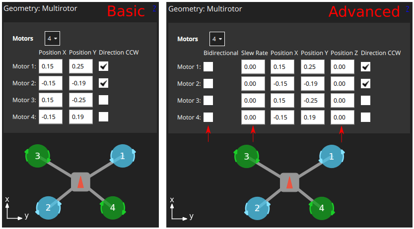
Yes, I think it’s cool too!!! PX4 allows for an off-center mass. This can be set up in the motor geometry. This will set up better motor mixing and allow better flight performance. You could change your load. Hang/Calibrate it. Update the motor geometry and get acceptable performance. Obviously, there would be a limit as to how far off the Center of Mass (CoM) can be from the frame center.

"Motor Position Coordinate System

The coordinate system for motor positions is FRD (in body frame), where the X axis points forward, the Y axis to the right and the Z axis down.

The origin is the vehicle’s centre-of-gravity (COG)."

I have updated the program to Aircraft Coordinate System. It is now posible to use the data from PX4 and ArduPilot IMU. However, I don’t have access to a drone with PX4 autopilot or ArduPilot.

So, I’m asking for some feedback.

These are the instructions I have for the README file on GitHub…

"How to use the Virtual Plumb Bob software:

Measure distance from the motors M1 and M3 in meters

Measure the distance from motors M1 and M4 in meters

The done will need to be connected to the QGC wirelessly.

The drone will need to hung from the M1 and M3 motors. The drone must be free and motionless during data collection.

imageimage

Collect IMU accelerometer data from each motor position. xacc, yacc , and zacc

Input data into the software.

EXAMPLE OF IMU DATA FROM QGC

This software version uses the Aircraft Coordinate System. However, the origin is at the geometric center of the X frame motors. The CoM location given is the distance from the geometric center.

The CoM is the center of all rotation of the drone. The with provided CoM location, the true distance from each motor to the CoM can be calculated. And the true and real amount of torque each motor provides can now be calculate.

In addition, if the location of the IMU is known, the distance from the CoM to the IMU can be calculated

PX4 autopilot: users should go to their PX4 Guide Hardware Selection & Setup tab and look in Actuator Allocation. Scroll down the page and review the Motor Position Coordinate System information. Then scroll to the Motor Geometry: Multicopper and follow the instructions using the data provided by the Virtual Plumb Bob software.

ArduPilot: At this time, it is unknown, by the author, where this data is used."

I have made a PX4 and ArduPiolt friendly version. Here is what it looks like.

So I have a Beta version and this is its output. The camera veiw can be rotated with a mouse.

I only know how to program in Matlab. My program is open source software.

If someone wants to collect their drone data, I can run the data and post the results?

The gravatational vector at any two points on the drone will be parallel. I simply move the IMU vector to the hanging poin and create a virtual Plumb bob. Where the two Plumb lines cross is the location of the center of gravity.

hi, how the check is working
need to record a ulog / via ros2 topic
did this application need that the drone flight ?
i like to check it on my drone

PX4 autopilot instructions

Use a meter stick and measure motors drive shaft to drive shaft

Measure distance from the motors M1 and M3 in meters

Measure the distance from motors M1 and M4 in meters

The done will need to be connected to the QGC wirelessly.

The drone will need to hung from the M1 and M3 motors. The drone must be free and motionless during data collection.

Collect IMU accelerometer data from each motor position. xacc, yacc , and zacc

Example of QGC

If you could take a drone photo of each motor position and the QGC that would help every one.

This what I have put in the ReadMe file

"PX4 autopilot: users should go to their PX4 Guide Hardware Selection & Setup tab and look in Actuator Allocation. Scroll down the page and review the Motor Position Coordinate System information. Then scroll to the Motor Geometry: Multicopper and follow the instructions using the data provided by the Virtual Plumb Bob software.

The CoG is the center of all rotation of the drone. With the provided CoG location, the true distance from each motor to the CoG can be calculated. And the true and real amount of torque each motor provides can be calculated."

I have been over at the ArduPilot form.

After explaining how the software works, the mathmatical process.

Someone of the ArduPilot team crated an app for ArdPilot for off the Center of Gravity. He used AI to crate the app. It apears to work. You don’t get any garphics but it updates the flight software through their misson planer.