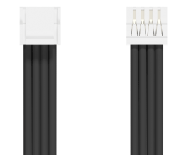
I am looking at this sensor to measure airspeed. It’s called Sensirion SDP3x Airspeed Sensor Kit (SDP33). The question I have is about this connector(JST-GH 4pins):
This is the cable that comes with it. Would it hook directly on to the PX4? Do I need to use some kind of a converter?
Those connectors are the newer standard that you will see on Pixhawk 4, Pixhawk 2.1 Cube and other newer variants. If you are using an older original Pixhawk then you will be accustomed to the DF13 type plugs (no snap and easily break). That said, it all just connects to the i2c port in either case so your second post has a splitter for that (i2c does not need its own port like telemetry or gps, etc) so you just need to plug in the sensor into your board’s i2c port and when it comes time to parameter setup bear in mind you need to look at that more closely since there are a few extra things needed with the sdp33 (tubing length namely).
What extra things were you talking about when you mentioned the tubing length thing for SDP33? I’d like to go through any material you may have on that.
You need to measure the tubing length and input it in. Don’t forget to also include the length of the pitot and You need to set the airspeed mode to take pressure drop into account. Both are parameters. Default is .2m of 1.5mm i.d. tubing+pitot but the tubing pressure drop option is not set by default.
The sdp33 is not a true differential pressured sensor but actually a flow meter technically so there’s a lot behind the scenes to make this work. Very accurate at low airspeed though.
We’ve been flying them with no problem. They work great. Just requires more setup on the frontend because of the tubing length addition but nothing else is different. You will sometime see a little negative airspeed when they are standing still in no wind but other than that they work pretty perfectly.
We’ve built a number of other airspeed sensors that have a useful range in the speeds most people fly (since the sensors being used often have much too high or large span of range which degrades accuracy since that is split over a given resolution). Example, a 1 PSI sensor (the 4525, ie the first digital sensor that most people still adopt), equates to a range of 6.89kPa. The issue is that, that sensor has 14bit resolution and it is near exponential the curve for airspeed measured to kPa. 1kPa ( or about .145 psi) is sufficient to about 42m/s (94 mph). So that entire range needs to be split over the total resolution leading to less granular reading.
Another way of thinking about this. If we have only so many digital numerical representations in a 12 or 14 bit sensor then effectively while the deviation of the sensor (accuracy might change dependent on a sensor), more psi (i.e. kPa) means more measurability (range). But not useful range and therefore less accuracy. Let me explain. 14 bits, so that is 16383/4 digital counts means that over the range of pressure the sensor senses we have that many digital representations of it. So the smaller the PSI (or kPa) in this case, the actually higher accuracy we achieve because (and this is approximate) 1 psi / 16383 = 0.00006103888177 psi per increment. Now if we have a sensor that ranges in 0.37 PSI, that same logic is 0.37/16383 = 0.00002258438625 PSI per bit. 2.7x the effective resolution representation since the vast majority of the 1 PSI sensor wouldn’t be used (the SDP is +/-0.21 PSI fyi and we don’t need the negative part at all).
Look at it this way. Assume for apple to apples comparison we will use 100% of the 0.37 psi sensor range and the therefore only 37% of the 1 psi sensor, we only have 37% of the digital representations to make up for the data we are looking at since the digital resolution is fixed. ~2/3 of the sensing range isn’t used but without an increase in digital representations (ie resolution), we are losing out significantly. We could model in the 2% accuracy against the 0.25% since all sensors have different accuracy number since in that case it is so significantly limited, it is irrelevant.
Heres the practical side of things though, that small of granular measurements isn’t needed because we are measuring airspeed driven from a less exact system (thrust, etc), we aren’t going to tell the plane to speed up to 17.643 m/s since that doesn’t really happen or matter in application but why would deploy, develop or use sensors that are not the best we have access to when there is no additional cost or complexity, often times there is actually a lower cost. It just requires work and testing on the hardware side and people to build them.
Use the SDP33, you’ll be happy. We’ve used it extensively on our test vehicles. When there is something better that is available in masses, that will be the switch and if it’s a true differential pressure sensor, you wouldn’t (most likely) need to add the tubing pressure data in.