I follow the Pixhawk instruction (by this link:Distance Sensors (Rangefinders) · PX4 v1.9.0 User Guide )
The sensor type is Lidar-Lite
I am curious about how to increase the sampling rate.
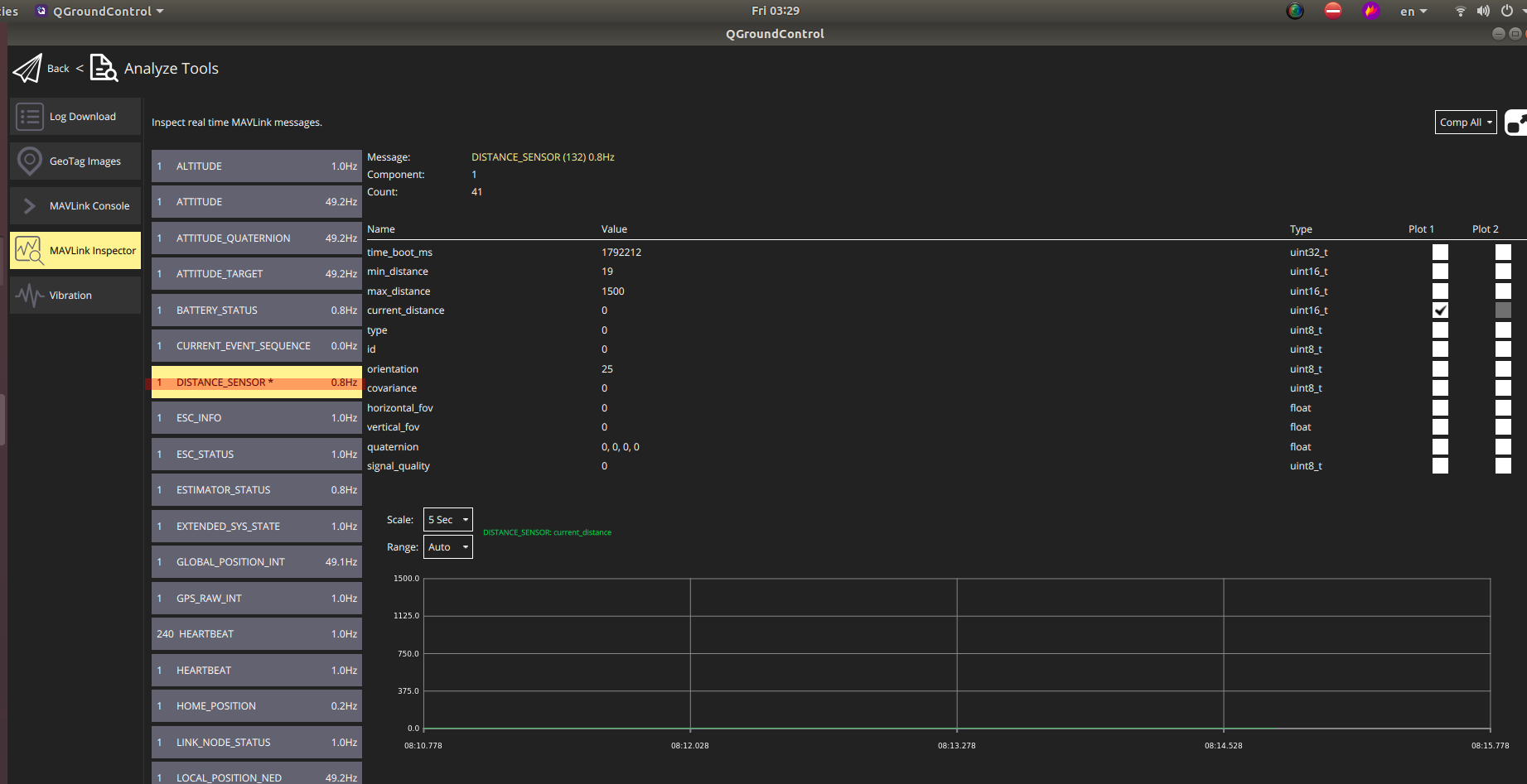
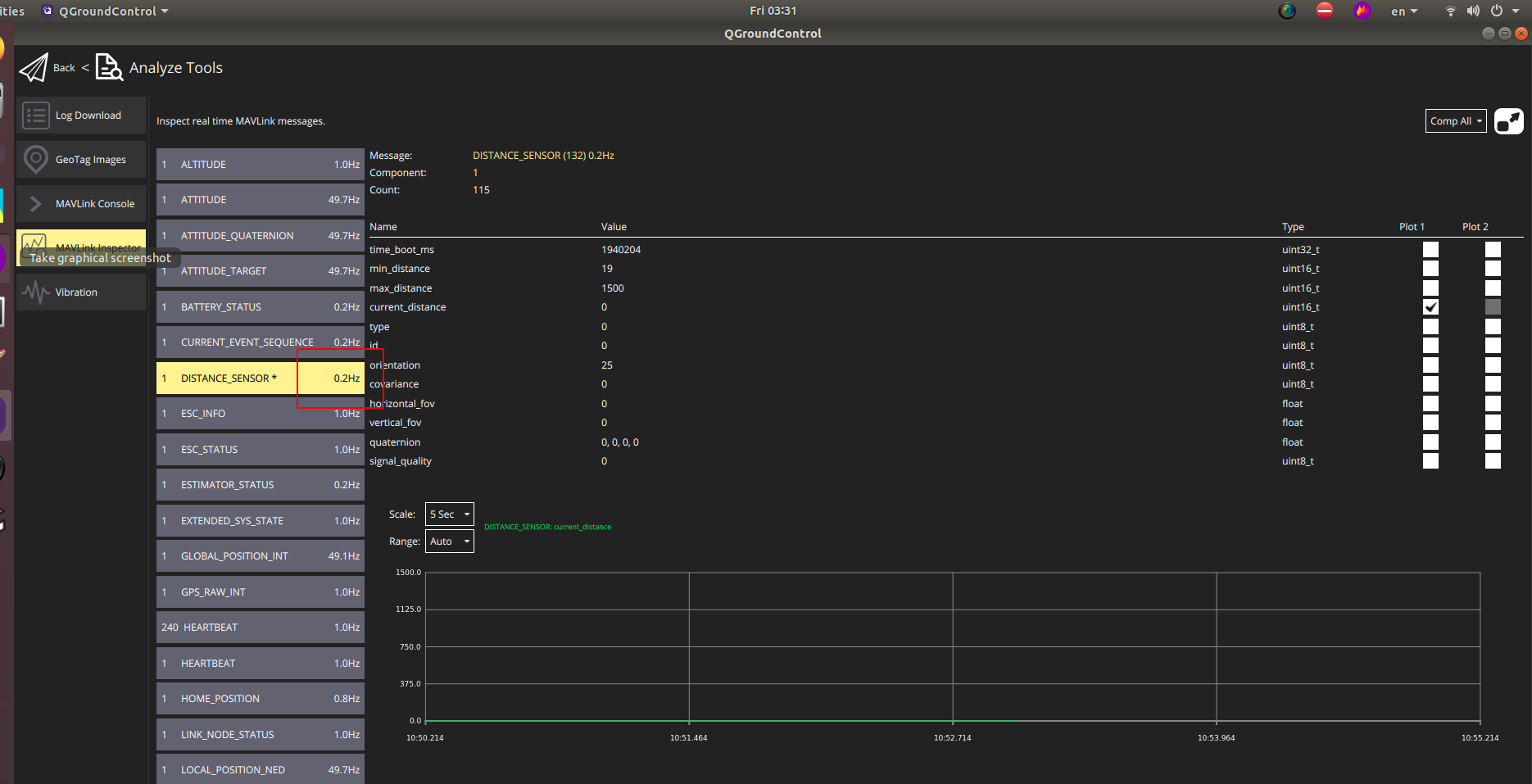
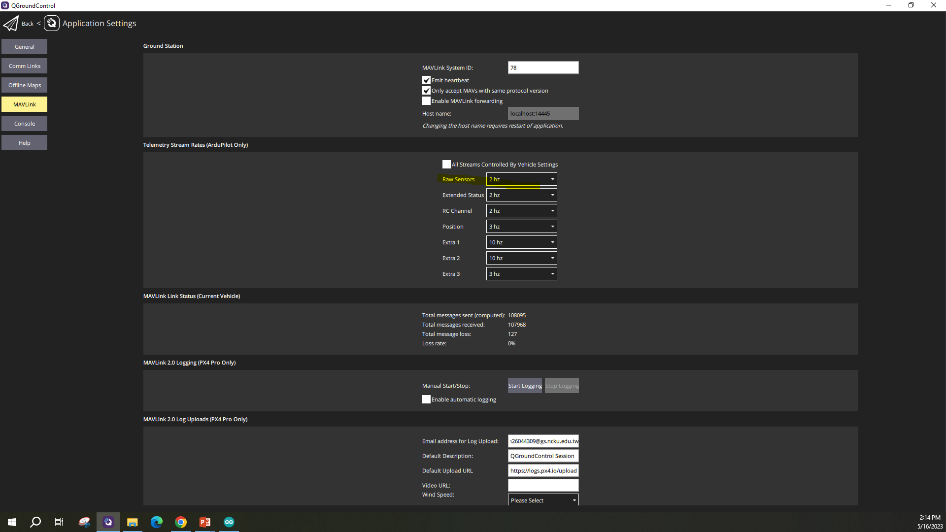
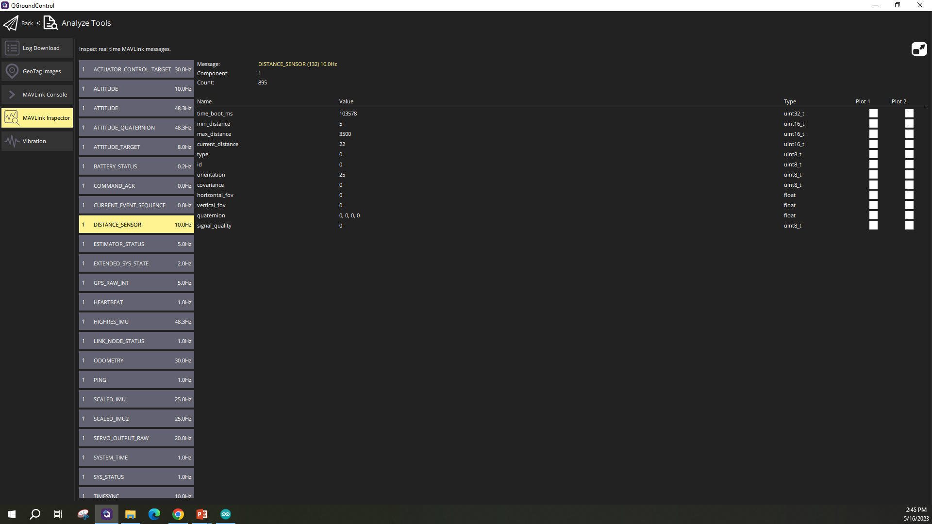
Also, I am confused why the QGroundControl Analyze Tools detect the distance sensor only 0.2~0.8 Hz, no matter in real world or simulation ( the simulation and real Lidar should be 10 hz)
Thanks a lot
P.SHow to Read Distance Sensor Data from MAVROS Topic Cannnot find the distance_sensor in the QGround control
In Ardupilot firmware, people suggest,
rosrun mavros mavsys message_interval --id XX --rate YY
by this way: How to adjust the sample rate of distance sensor (rangefinder) - ArduCopter - ArduPilot Discourse
I also examine mavlink_main.cpp by this way: Increase stream rate of HIGHRES_IMU message
Someone change the sampling rate of IMU by edit this file /fs/microsd/etc/extras.txtSystem Startup | PX4 User Guide
Increase the sampling rate in Gazebo simulation increase sensor rate SITL · Issue #980 · mavlink/mavros · GitHub
How to change the correct publisher name: How to use distance_sensor? send distance Sensor data to FCU for use as altitude · Issue #664 · mavlink/mavros · GitHub
@AlexWUrobot …I am also trying to put my distance sensor VL53L0x into operation for collision prevention. QGC shows the distance measured but the drone in POSITION mode does not handle collision detection !! Any clues ?
In your case, you have to make sure that the drone is flying in POSITION MODE for the distance sensor to work .
Where did you install MAVROS. is it on a Raspberry Pi ?
Thanks for the replyMAVROS Offboard control example (Python) | PX4 User Guide
great info !! Actually i am a bit confused . Is it better to go the MavROS way or the MAVSDK way to control the Quadcopter in offboard mode …
I have not tried MAVSDK, but I think this link will be helpful:Difference MAVLink and MAVROS
She said:
MAVROS is the bridge between MAVLink and ROS. If you’re using ROS for whatever robotics you’re doing, then MAVROS is great.the Dronecode SDK
The solution may be to edit the SD card in the Pixhawk
cd /fs/microsd/etc
echo "mavlink stream -d /dev/ttyACM0 -s HIGHRES_IMU -r 100" > extras.txt
opened 03:37PM - 13 Nov 19 UTC
### Issue details
I need to change the update rate of my 3DR Pixhawk IMU from… 50 Hz to 100 Hz. I've tried with `rosrun mavros mavsys rate --all 100` from terminal but it still remains at 50.
Can somebody show me how to do this? Thanks.
### MAVROS version and platform
Mavros: ?0.18.4?
ROS: Melodic
Ubuntu: 18.04
### Autopilot type and version
[ ] ArduPilot
[ X ] PX4
Version: Fimware 1.9.2
### Node logs
```
$ roslaunch mavros px4.launch
... logging to /home/francesco/.ros/log/9f8841d2-0631-11ea-bf51-7cb0c2639a2f/roslaunch-Enterprise-Ubuntu-5233.log
Checking log directory for disk usage. This may take awhile.
Press Ctrl-C to interrupt
Done checking log file disk usage. Usage is <1GB.
/opt/ros/melodic/lib/python2.7/dist-packages/roslaunch/loader.py:412: YAMLLoadWarning: calling yaml.load() without Loader=... is deprecated, as the default Loader is unsafe. Please read https://msg.pyyaml.org/load for full details.
data = yaml.load(text)
started roslaunch server http://Enterprise-Ubuntu:42721/
SUMMARY
========
CLEAR PARAMETERS
* /mavros/
PARAMETERS
* /mavros/cmd/use_comp_id_system_control: False
* /mavros/conn/heartbeat_rate: 1.0
* /mavros/conn/system_time_rate: 1.0
* /mavros/conn/timeout: 10.0
* /mavros/conn/timesync_rate: 10.0
* /mavros/distance_sensor/hrlv_ez4_pub/field_of_view: 0.0
* /mavros/distance_sensor/hrlv_ez4_pub/frame_id: hrlv_ez4_sonar
* /mavros/distance_sensor/hrlv_ez4_pub/id: 0
* /mavros/distance_sensor/hrlv_ez4_pub/orientation: PITCH_270
* /mavros/distance_sensor/hrlv_ez4_pub/send_tf: True
* /mavros/distance_sensor/hrlv_ez4_pub/sensor_position/x: 0.0
* /mavros/distance_sensor/hrlv_ez4_pub/sensor_position/y: 0.0
* /mavros/distance_sensor/hrlv_ez4_pub/sensor_position/z: -0.1
* /mavros/distance_sensor/laser_1_sub/id: 3
* /mavros/distance_sensor/laser_1_sub/orientation: PITCH_270
* /mavros/distance_sensor/laser_1_sub/subscriber: True
* /mavros/distance_sensor/lidarlite_pub/field_of_view: 0.0
* /mavros/distance_sensor/lidarlite_pub/frame_id: lidarlite_laser
* /mavros/distance_sensor/lidarlite_pub/id: 1
* /mavros/distance_sensor/lidarlite_pub/orientation: PITCH_270
* /mavros/distance_sensor/lidarlite_pub/send_tf: True
* /mavros/distance_sensor/lidarlite_pub/sensor_position/x: 0.0
* /mavros/distance_sensor/lidarlite_pub/sensor_position/y: 0.0
* /mavros/distance_sensor/lidarlite_pub/sensor_position/z: -0.1
* /mavros/distance_sensor/sonar_1_sub/id: 2
* /mavros/distance_sensor/sonar_1_sub/orientation: PITCH_270
* /mavros/distance_sensor/sonar_1_sub/subscriber: True
* /mavros/fake_gps/eph: 2.0
* /mavros/fake_gps/epv: 2.0
* /mavros/fake_gps/fix_type: 3
* /mavros/fake_gps/geo_origin/alt: 408.0
* /mavros/fake_gps/geo_origin/lat: 47.3667
* /mavros/fake_gps/geo_origin/lon: 8.55
* /mavros/fake_gps/gps_rate: 5.0
* /mavros/fake_gps/mocap_transform: True
* /mavros/fake_gps/satellites_visible: 5
* /mavros/fake_gps/tf/child_frame_id: fix
* /mavros/fake_gps/tf/frame_id: map
* /mavros/fake_gps/tf/listen: False
* /mavros/fake_gps/tf/rate_limit: 10.0
* /mavros/fake_gps/tf/send: False
* /mavros/fake_gps/use_mocap: True
* /mavros/fake_gps/use_vision: False
* /mavros/fcu_protocol: v2.0
* /mavros/fcu_url: /dev/ttyACM0:57600
* /mavros/gcs_url:
* /mavros/global_position/child_frame_id: base_link
* /mavros/global_position/frame_id: map
* /mavros/global_position/gps_uere: 1.0
* /mavros/global_position/rot_covariance: 99999.0
* /mavros/global_position/tf/child_frame_id: base_link
* /mavros/global_position/tf/frame_id: map
* /mavros/global_position/tf/global_frame_id: earth
* /mavros/global_position/tf/send: False
* /mavros/global_position/use_relative_alt: True
* /mavros/image/frame_id: px4flow
* /mavros/imu/angular_velocity_stdev: 0.0003490659 // 0...
* /mavros/imu/frame_id: base_link
* /mavros/imu/linear_acceleration_stdev: 0.0003
* /mavros/imu/magnetic_stdev: 0.0
* /mavros/imu/orientation_stdev: 1.0
* /mavros/landing_target/camera/fov_x: 2.0071286398
* /mavros/landing_target/camera/fov_y: 2.0071286398
* /mavros/landing_target/image/height: 480
* /mavros/landing_target/image/width: 640
* /mavros/landing_target/land_target_type: VISION_FIDUCIAL
* /mavros/landing_target/listen_lt: False
* /mavros/landing_target/mav_frame: LOCAL_NED
* /mavros/landing_target/target_size/x: 0.3
* /mavros/landing_target/target_size/y: 0.3
* /mavros/landing_target/tf/child_frame_id: camera_center
* /mavros/landing_target/tf/frame_id: landing_target
* /mavros/landing_target/tf/listen: False
* /mavros/landing_target/tf/rate_limit: 10.0
* /mavros/landing_target/tf/send: True
* /mavros/local_position/frame_id: map
* /mavros/local_position/tf/child_frame_id: base_link
* /mavros/local_position/tf/frame_id: map
* /mavros/local_position/tf/send: False
* /mavros/local_position/tf/send_fcu: False
* /mavros/mission/pull_after_gcs: True
* /mavros/mocap/use_pose: True
* /mavros/mocap/use_tf: False
* /mavros/odometry/in/child_frame_id: base_link
* /mavros/odometry/in/frame_id: odom
* /mavros/odometry/in/frame_tf/body_frame_orientation: flu
* /mavros/odometry/in/frame_tf/local_frame: local_origin_ned
* /mavros/odometry/out/frame_tf/body_frame_orientation: frd
* /mavros/odometry/out/frame_tf/local_frame: vision_ned
* /mavros/plugin_blacklist: ['safety_area', '...
* /mavros/plugin_whitelist: []
* /mavros/px4flow/frame_id: px4flow
* /mavros/px4flow/ranger_fov: 0.118682
* /mavros/px4flow/ranger_max_range: 5.0
* /mavros/px4flow/ranger_min_range: 0.3
* /mavros/safety_area/p1/x: 1.0
* /mavros/safety_area/p1/y: 1.0
* /mavros/safety_area/p1/z: 1.0
* /mavros/safety_area/p2/x: -1.0
* /mavros/safety_area/p2/y: -1.0
* /mavros/safety_area/p2/z: -1.0
* /mavros/setpoint_accel/send_force: False
* /mavros/setpoint_attitude/reverse_thrust: False
* /mavros/setpoint_attitude/tf/child_frame_id: target_attitude
* /mavros/setpoint_attitude/tf/frame_id: map
* /mavros/setpoint_attitude/tf/listen: False
* /mavros/setpoint_attitude/tf/rate_limit: 100.0
* /mavros/setpoint_attitude/use_quaternion: False
* /mavros/setpoint_position/mav_frame: LOCAL_NED
* /mavros/setpoint_position/tf/child_frame_id: target_position
* /mavros/setpoint_position/tf/frame_id: map
* /mavros/setpoint_position/tf/listen: False
* /mavros/setpoint_position/tf/rate_limit: 100.0
* /mavros/setpoint_raw/thrust_scaling: 1.0
* /mavros/setpoint_velocity/mav_frame: LOCAL_NED
* /mavros/startup_px4_usb_quirk: True
* /mavros/sys/disable_diag: False
* /mavros/sys/min_voltage: 10.0
* /mavros/target_component_id: 1
* /mavros/target_system_id: 1
* /mavros/tdr_radio/low_rssi: 40
* /mavros/time/time_ref_source: fcu
* /mavros/time/timesync_avg_alpha: 0.6
* /mavros/time/timesync_mode: MAVLINK
* /mavros/vibration/frame_id: base_link
* /mavros/vision_pose/tf/child_frame_id: vision_estimate
* /mavros/vision_pose/tf/frame_id: map
* /mavros/vision_pose/tf/listen: False
* /mavros/vision_pose/tf/rate_limit: 10.0
* /mavros/vision_speed/listen_twist: True
* /mavros/vision_speed/twist_cov: True
* /mavros/wheel_odometry/child_frame_id: base_link
* /mavros/wheel_odometry/count: 2
* /mavros/wheel_odometry/frame_id: map
* /mavros/wheel_odometry/send_raw: True
* /mavros/wheel_odometry/send_twist: False
* /mavros/wheel_odometry/tf/child_frame_id: base_link
* /mavros/wheel_odometry/tf/frame_id: map
* /mavros/wheel_odometry/tf/send: True
* /mavros/wheel_odometry/use_rpm: False
* /mavros/wheel_odometry/vel_error: 0.1
* /mavros/wheel_odometry/wheel0/radius: 0.05
* /mavros/wheel_odometry/wheel0/x: 0.0
* /mavros/wheel_odometry/wheel0/y: -0.15
* /mavros/wheel_odometry/wheel1/radius: 0.05
* /mavros/wheel_odometry/wheel1/x: 0.0
* /mavros/wheel_odometry/wheel1/y: 0.15
* /rosdistro: melodic
* /rosversion: 1.14.3
NODES
/
mavros (mavros/mavros_node)
auto-starting new master
process[master]: started with pid [5243]
ROS_MASTER_URI=http://localhost:11311
setting /run_id to 9f8841d2-0631-11ea-bf51-7cb0c2639a2f
process[rosout-1]: started with pid [5254]
started core service [/rosout]
process[mavros-2]: started with pid [5262]
[ INFO] [1573662079.656099451]: FCU URL: /dev/ttyACM0:57600
[ INFO] [1573662079.657818878]: serial0: device: /dev/ttyACM0 @ 57600 bps
[ INFO] [1573662079.658671139]: GCS bridge disabled
[ INFO] [1573662079.668287823]: Plugin 3dr_radio loaded
[ INFO] [1573662079.670016509]: Plugin 3dr_radio initialized
[ INFO] [1573662079.670234880]: Plugin actuator_control loaded
[ INFO] [1573662079.673824565]: Plugin actuator_control initialized
[ INFO] [1573662079.676823138]: Plugin adsb loaded
[ INFO] [1573662079.679591729]: Plugin adsb initialized
[ INFO] [1573662079.679736826]: Plugin altitude loaded
[ INFO] [1573662079.680577553]: Plugin altitude initialized
[ INFO] [1573662079.680694493]: Plugin cam_imu_sync loaded
[ INFO] [1573662079.681215995]: Plugin cam_imu_sync initialized
[ INFO] [1573662079.681369384]: Plugin command loaded
[ INFO] [1573662079.686094142]: Plugin command initialized
[ INFO] [1573662079.686310664]: Plugin companion_process_status loaded
[ INFO] [1573662079.688988588]: Plugin companion_process_status initialized
[ INFO] [1573662079.689143500]: Plugin debug_value loaded
[ INFO] [1573662079.692692067]: Plugin debug_value initialized
[ INFO] [1573662079.692721989]: Plugin distance_sensor blacklisted
[ INFO] [1573662079.692852557]: Plugin fake_gps loaded
[ INFO] [1573662079.703168760]: Plugin fake_gps initialized
[ INFO] [1573662079.703309628]: Plugin ftp loaded
[ INFO] [1573662079.709523824]: Plugin ftp initialized
[ INFO] [1573662079.709638065]: Plugin global_position loaded
[ INFO] [1573662079.720811903]: Plugin global_position initialized
[ INFO] [1573662079.720962746]: Plugin gps_rtk loaded
[ INFO] [1573662079.722741699]: Plugin gps_rtk initialized
[ INFO] [1573662079.722921430]: Plugin hil loaded
[ INFO] [1573662079.731383343]: Plugin hil initialized
[ INFO] [1573662079.731495199]: Plugin home_position loaded
[ INFO] [1573662079.733835446]: Plugin home_position initialized
[ INFO] [1573662079.733994260]: Plugin imu loaded
[ INFO] [1573662079.739424375]: Plugin imu initialized
[ INFO] [1573662079.739531799]: Plugin landing_target loaded
[ INFO] [1573662079.747782105]: Plugin landing_target initialized
[ INFO] [1573662079.747929336]: Plugin local_position loaded
[ INFO] [1573662079.753258482]: Plugin local_position initialized
[ INFO] [1573662079.753415197]: Plugin log_transfer loaded
[ INFO] [1573662079.756249202]: Plugin log_transfer initialized
[ INFO] [1573662079.756393930]: Plugin manual_control loaded
[ INFO] [1573662079.759077952]: Plugin manual_control initialized
[ INFO] [1573662079.759176190]: Plugin mocap_pose_estimate loaded
[ INFO] [1573662079.761567698]: Plugin mocap_pose_estimate initialized
[ INFO] [1573662079.761662659]: Plugin mount_control loaded
[ INFO] [1573662079.763184661]: Plugin mount_control initialized
[ INFO] [1573662079.763270277]: Plugin obstacle_distance loaded
[ INFO] [1573662079.764577824]: Plugin obstacle_distance initialized
[ INFO] [1573662079.764663047]: Plugin odom loaded
[ INFO] [1573662079.769220272]: Plugin odom initialized
[ INFO] [1573662079.769407834]: Plugin param loaded
[ INFO] [1573662079.771911625]: Plugin param initialized
[ INFO] [1573662079.772008356]: Plugin px4flow loaded
[ INFO] [1573662079.777775497]: Plugin px4flow initialized
[ INFO] [1573662079.777832945]: Plugin rangefinder blacklisted
[ INFO] [1573662079.778001135]: Plugin rc_io loaded
[ INFO] [1573662079.782147715]: Plugin rc_io initialized
[ INFO] [1573662079.782185354]: Plugin safety_area blacklisted
[ INFO] [1573662079.782305933]: Plugin setpoint_accel loaded
[ INFO] [1573662079.785404626]: Plugin setpoint_accel initialized
[ INFO] [1573662079.785592574]: Plugin setpoint_attitude loaded
[ INFO] [1573662079.793386243]: Plugin setpoint_attitude initialized
[ INFO] [1573662079.793545462]: Plugin setpoint_position loaded
[ INFO] [1573662079.801512386]: Plugin setpoint_position initialized
[ INFO] [1573662079.801628355]: Plugin setpoint_raw loaded
[ INFO] [1573662079.807218690]: Plugin setpoint_raw initialized
[ INFO] [1573662079.807359336]: Plugin setpoint_velocity loaded
[ INFO] [1573662079.811608805]: Plugin setpoint_velocity initialized
[ INFO] [1573662079.811879909]: Plugin sys_status loaded
[ INFO] [1573662079.818481006]: Plugin sys_status initialized
[ INFO] [1573662079.818604306]: Plugin sys_time loaded
[ INFO] [1573662079.822532412]: TM: Timesync mode: MAVLINK
[ INFO] [1573662079.823434894]: Plugin sys_time initialized
[ INFO] [1573662079.823557027]: Plugin trajectory loaded
[ INFO] [1573662079.827016129]: Plugin trajectory initialized
[ INFO] [1573662079.827122485]: Plugin vfr_hud loaded
[ INFO] [1573662079.827564281]: Plugin vfr_hud initialized
[ INFO] [1573662079.827587796]: Plugin vibration blacklisted
[ INFO] [1573662079.827679201]: Plugin vision_pose_estimate loaded
[ INFO] [1573662079.832146564]: Plugin vision_pose_estimate initialized
[ INFO] [1573662079.832230922]: Plugin vision_speed_estimate loaded
[ INFO] [1573662079.834574641]: Plugin vision_speed_estimate initialized
[ INFO] [1573662079.834694576]: Plugin waypoint loaded
[ INFO] [1573662079.839075768]: Plugin waypoint initialized
[ INFO] [1573662079.839138598]: Plugin wheel_odometry blacklisted
[ INFO] [1573662079.839311319]: Plugin wind_estimation loaded
[ INFO] [1573662079.839938926]: Plugin wind_estimation initialized
[ INFO] [1573662079.840002397]: Autostarting mavlink via USB on PX4
[ INFO] [1573662079.840114082]: Built-in SIMD instructions: SSE, SSE2
[ INFO] [1573662079.840133882]: Built-in MAVLink package version: 2019.9.9
[ INFO] [1573662079.840199602]: Known MAVLink dialects: common ardupilotmega ASLUAV autoquad icarous matrixpilot paparazzi slugs standard uAvionix ualberta
[ INFO] [1573662079.840240252]: MAVROS started. MY ID 1.240, TARGET ID 1.1
[ INFO] [1573662079.935933482]: IMU: Scaled IMU message used.
[ERROR] [1573662079.944128361]: ODOM: Ex: Could not find a connection between 'local_origin_ned' and 'fcu' because they are not part of the same tree.Tf has two or more unconnected trees.
[ INFO] [1573662080.004054503]: IMU: High resolution IMU detected!
[ INFO] [1573662080.005016911]: IMU: Attitude quaternion IMU detected!
[ INFO] [1573662080.487696816]: CON: Got HEARTBEAT, connected. FCU: PX4 Autopilot
[ INFO] [1573662080.514897068]: IMU: High resolution IMU detected!
[ INFO] [1573662080.515470700]: IMU: Attitude quaternion IMU detected!
[ERROR] [1573662080.814692169]: FCU: Data link lost
[ INFO] [1573662080.906314290]: FCU: Onboard controller regained
[ERROR] [1573662080.980156568]: ODOM: Ex: Could not find a connection between 'local_origin_ned' and 'fcu' because they are not part of the same tree.Tf has two or more unconnected trees.
[ INFO] [1573662081.493774084]: VER: 1.1: Capabilities 0x000000000000e4ef
[ INFO] [1573662081.493921415]: VER: 1.1: Flight software: 010902ff (106905871d000000)
[ INFO] [1573662081.493999177]: VER: 1.1: Middleware software: 010902ff (106905871d000000)
[ INFO] [1573662081.494088606]: VER: 1.1: OS software: 071c00ff (423371c7d4012e72)
[ INFO] [1573662081.494167688]: VER: 1.1: Board hardware: 00000011
[ INFO] [1573662081.494232908]: VER: 1.1: VID/PID: 26ac:0011
[ INFO] [1573662081.494285964]: VER: 1.1: UID: 3034510736353832
[ WARN] [1573662081.496977880]: CMD: Unexpected command 520, result 0
[ERROR] [1573662081.996994591]: ODOM: Ex: Could not find a connection between 'local_origin_ned' and 'fcu' because they are not part of the same tree.Tf has two or more unconnected trees.
[ERROR] [1573662083.027204250]: ODOM: Ex: Could not find a connection between 'local_origin_ned' and 'fcu' because they are not part of the same tree.Tf has two or more unconnected trees.
[ERROR] [1573662084.027444532]: ODOM: Ex: Could not find a connection between 'local_origin_ned' and 'fcu' because they are not part of the same tree.Tf has two or more unconnected trees.
[ERROR] [1573662085.061106727]: ODOM: Ex: Could not find a connection between 'local_origin_ned' and 'fcu' because they are not part of the same tree.Tf has two or more unconnected trees.
[ERROR] [1573662086.095190534]: ODOM: Ex: Could not find a connection between 'local_origin_ned' and 'fcu' because they are not part of the same tree.Tf has two or more unconnected trees.
[ERROR] [1573662087.096480620]: ODOM: Ex: Could not find a connection between 'local_origin_ned' and 'fcu' because they are not part of the same tree.Tf has two or more unconnected trees.
[ERROR] [1573662088.097932593]: ODOM: Ex: Could not find a connection between 'local_origin_ned' and 'fcu' because they are not part of the same tree.Tf has two or more unconnected trees.
[ERROR] [1573662089.128315701]: ODOM: Ex: Could not find a connection between 'local_origin_ned' and 'fcu' because they are not part of the same tree.Tf has two or more unconnected trees.
[ERROR] [1573662090.129052823]: ODOM: Ex: Could not find a connection between 'local_origin_ned' and 'fcu' because they are not part of the same tree.Tf has two or more unconnected trees.
[ INFO] [1573662090.488257328]: HP: requesting home position
```
### Diagnostics
```
header:
seq: 8
stamp:
secs: 1573662083
nsecs: 341054933
frame_id: ''
status:
-
level: 0
name: "mavros: FCU connection"
message: "connected"
hardware_id: "/dev/ttyACM0:57600"
values:
-
key: "Received packets:"
value: "1175"
-
key: "Dropped packets:"
value: "0"
-
key: "Buffer overruns:"
value: "0"
-
key: "Parse errors:"
value: "0"
-
key: "Rx sequence number:"
value: "128"
-
key: "Tx sequence number:"
value: "71"
-
key: "Rx total bytes:"
value: "66885"
-
key: "Tx total bytes:"
value: "1896"
-
key: "Rx speed:"
value: "34703.000000"
-
key: "Tx speed:"
value: "835.000000"
-
level: 2
name: "mavros: GPS"
message: "No satellites"
hardware_id: "/dev/ttyACM0:57600"
values:
-
key: "Satellites visible"
value: "0"
-
key: "Fix type"
value: "0"
-
key: "EPH (m)"
value: "Unknown"
-
key: "EPV (m)"
value: "Unknown"
-
level: 0
name: "mavros: Heartbeat"
message: "Normal"
hardware_id: "/dev/ttyACM0:57600"
values:
-
key: "Heartbeats since startup"
value: "3"
-
key: "Frequency (Hz)"
value: "0.850095"
-
key: "Vehicle type"
value: "Quadrotor"
-
key: "Autopilot type"
value: "PX4 Autopilot"
-
key: "Mode"
value: "MANUAL"
-
key: "System status"
value: "Standby"
-
level: 2
name: "mavros: System"
message: "Sensor health"
hardware_id: "/dev/ttyACM0:57600"
values:
-
key: "Sensor present"
value: "0x0006002F"
-
key: "Sensor enabled"
value: "0x0021000F"
-
key: "Sensor health"
value: "0x0006002F"
-
key: "3D gyro"
value: "Ok"
-
key: "3D accelerometer"
value: "Ok"
-
key: "3D magnetometer"
value: "Ok"
-
key: "absolute pressure"
value: "Ok"
-
key: "rc receiver"
value: "Fail"
-
key: "AHRS subsystem health"
value: "Fail"
-
key: "CPU Load (%)"
value: "47.9"
-
key: "Drop rate (%)"
value: "0.0"
-
key: "Errors comm"
value: "0"
-
key: "Errors count #1"
value: "0"
-
key: "Errors count #2"
value: "0"
-
key: "Errors count #3"
value: "0"
-
key: "Errors count #4"
value: "0"
-
level: 0
name: "mavros: Battery"
message: "Normal"
hardware_id: "/dev/ttyACM0:57600"
values:
-
key: "Voltage"
value: "65.54"
-
key: "Current"
value: "-0.0"
-
key: "Remaining"
value: "-1.0"
-
level: 0
name: "mavros: Time Sync"
message: "Normal"
hardware_id: "/dev/ttyACM0:57600"
values:
-
key: "Timesyncs since startup"
value: "35"
-
key: "Frequency (Hz)"
value: "9.936432"
-
key: "Last RTT (ms)"
value: "1.598668"
-
key: "Mean RTT (ms)"
value: "1.001017"
-
key: "Last remote time (s)"
value: "392.844721000"
-
key: "Estimated time offset (s)"
value: "1573661690.480628252"
---
```
### Check ID
```
OK. I got messages from 1:1.
---
Received 6075 messages, from 1 addresses
sys:comp list of messages
1:1 0, 1, 2, 4, 140, 141, 147, 26, 30, 31, 32, 36, 74, 331, 77, 83, 340, 230, 105, 111, 241, 116, 245
```
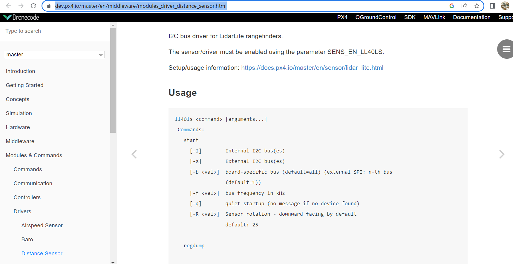
What about accessing Lidarlite from the Mavlink console menu in QGC . There is an option to adjust the bus frequency
Thanks for the info. I also found this but the unit is kHz, so I guess it may be for communication rate, instead of sampling rate. Distance Sensor · PX4 Developer Guide
I will still try that. Thanks for the reminder again.
I found some people have the similar issuelidar lite slow read rate · Issue #367 · intel-aero/meta-intel-aero · GitHub
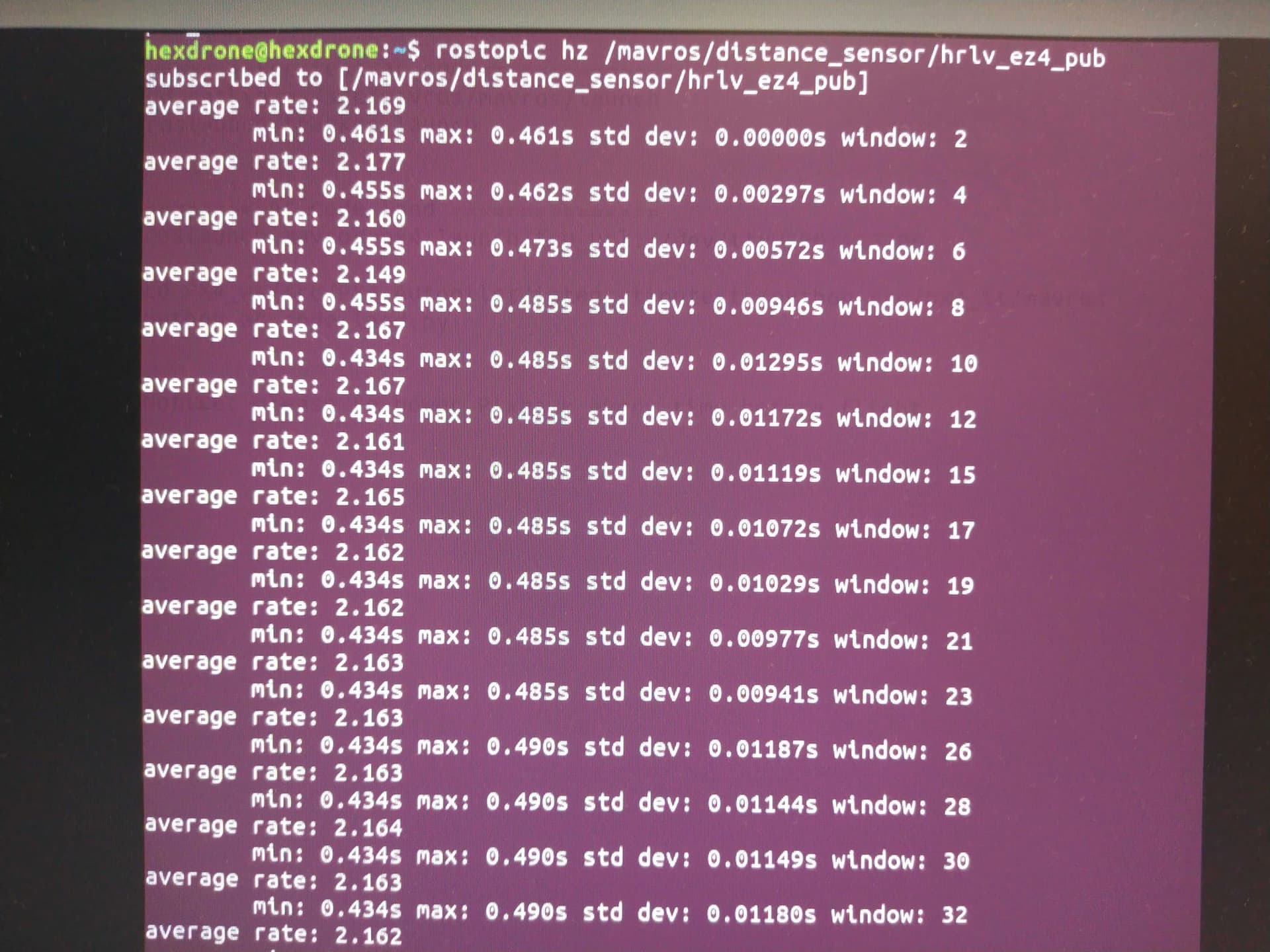
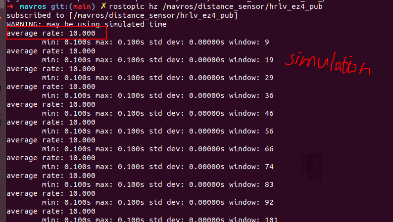
My publish rate of (/mavros/distance_sensor/lidarlite_pub) is 10 hz in the simulation, but only 2 Hz in the real world, when readling from Pixhawk 4 (fmuV5).
If we assume the lidar-lite works well (default sampling rate 10Hz)
Thus, I screenshot the other parameters of distance sensor (rangefinder) in the QGroundControl
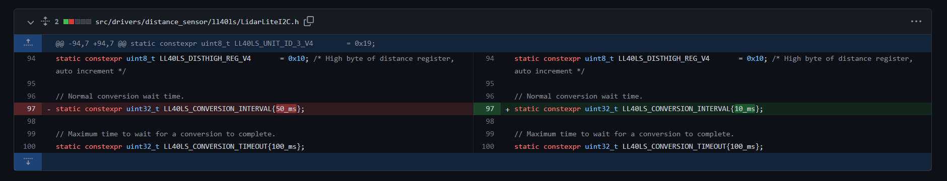
I also guess the issue may be due to this revision on LidarLiteI2C.h increased rate of Lidar Lite driver over I2C · PX4/PX4-Autopilot@7ca16cd · GitHub
Maybe, I should change it to 10 ms and then
cd PX4-Autopilot
make px4_fmu-v5_default
ref: Building PX4 Software | PX4 User Guide
Great info…My concern is how do you built the px4 after changing the value …Do you have a complete procedure for doing this through Nuttx shell
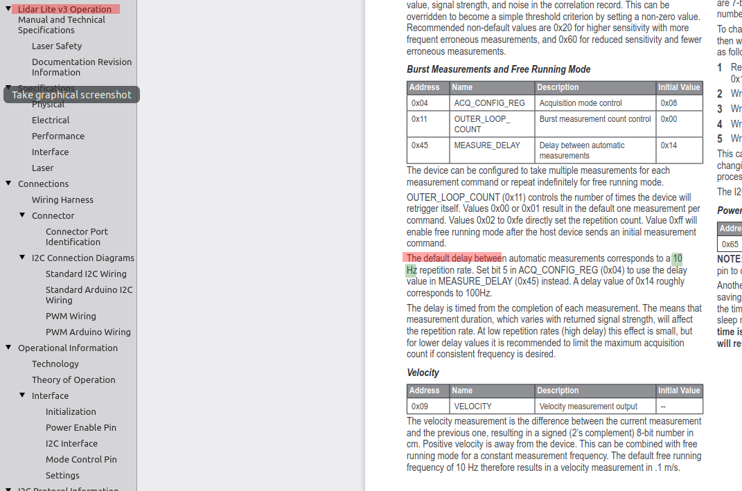
I am still working for this issue.https://static.garmin.com/pumac/LIDAR_Lite_v3_Operation_Manual_and_Technical_Specifications.pdf
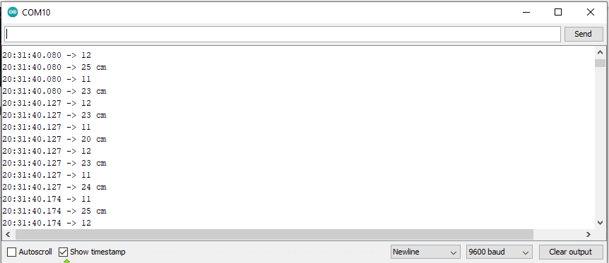
After Arduino measurement, the sampling rate is about 80~90 Hz.Arduino Test Lidar lite v3 sampling rate 2023 05 13 - YouTube
The code is used from the link:
https://learn.sparkfun.com/tutorials/lidar-lite-v3-hookup-guide/all
/**
 * LIDARLite I2C Example
 * Author: Garmin
 * Modified by: Shawn Hymel (SparkFun Electronics)
 * Date: June 29, 2017
 *
 * Read distance from LIDAR-Lite v3 over I2C
 *
 * See the Operation Manual for wiring diagrams and more information:
 * http://static.garmin.com/pumac/LIDAR_Lite_v3_Operation_Manual_and_Technical_Specifications.pdf
 */

#include <Wire.h>
#include <LIDARLite.h>

// Globals
LIDARLite lidarLite;
int cal_cnt = 0;
unsigned long previousMillis = 0; // variable to store the previous time

void setup()
{
  Serial.begin(9600); // Initialize serial connection to display distance readings

  lidarLite.begin(0, true); // Set configuration to default and I2C to 400 kHz
  lidarLite.configure(0); // Change this number to try out alternate configurations
}

void loop()
{
  int dist;
  unsigned long currentMillis = millis(); // varia

  // At the beginning of every 100 readings,
  // take a measurement with receiver bias correction
  if ( cal_cnt == 0 ) {
    dist = lidarLite.distance();      // With bias correction
  } else {
    dist = lidarLite.distance(false); // Without bias correction
  }

  // Increment reading counter
  cal_cnt++;
  cal_cnt = cal_cnt % 100;

  // Display distance
  Serial.print(dist);
  Serial.println(" cm");

  Serial.println(currentMillis - previousMillis); // display time elapsed for line 1
  previousMillis = currentMillis;

  //delay(10);
}```
I think I find something useful in the QGroundcontrol.
rosrun mavros mavsys rate --all 50
ref: increase/change mavros local_position pose publish frequency - ROS Answers: Open Source Q&A Forum
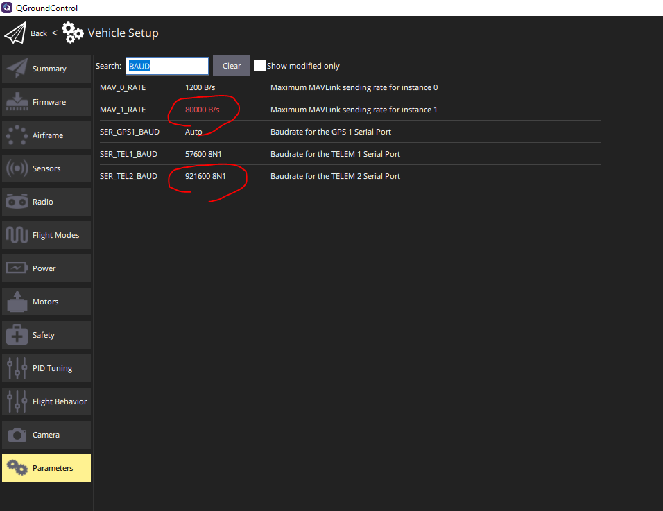
I find
Thus, the lidar works well and QGroundcontrol works OK.
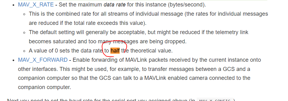
There is the solution !!!
PX4-autopilot automatically half-size the data , if the communication is too low.
P.S.