Hello PX4 Community,
I am developing a custom Standard VTOL in Gazebo (PX4 SITL). I have hit a persistent issue where the Pusher Motor (Motor 5) generates a violent Yaw Spin and Vibration instead of forward thrust, making transition impossible.
1. The Setup & Constraint
-
Multicopter Mode: Works perfectly (Stable hover).
-
Base Link: Due to the mesh orientation, my
base_linkis rotated by 180 degrees in Yaw (0 0 3.14159). -
Pusher Joint: I want the pusher to spin around the Body X-axis (Forward).
2. The Problem Even though I copied the Inertia values and Joint Axis from the working standard_vtol model, my vehicle instantly becomes unstable (huge vibration in Raw Acceleration and Yaw Rate) as soon as the pusher spins up.
2-1. What I have tried (Extensive Debugging) I suspected a frame mismatch between the Joint, Link, and Inertia, so I tried the following:
-
Reference Model Approach: Like the
standard_vtol, I rotated the link so the local Z-axis points forward and set the Joint Axis to Z (0 0 1). → Same spinning issue. -
Physics Isolation: I disabled Gravity (
<gravity>0</gravity>) and removed all Aerodynamic Plugins (LiftDrag). → The violent spin persists, confirming it is a mechanical/inertial collision, not aerodynamic. -
Mesh Editing: I even modified the
.daemesh file directly to align the propeller blades along the Z-axis and set the forward direction to X to match the frame. → No improvement. -
Inertia Matrix: I tried swapping Ixx and Izz values to match the visual geometry.
3. What I have analyzed I compared my setup with the standard_vtol.
-
Standard VTOL (Working):
-
base_linkpose:0 0 0 -
rotor_pullerinertia:ixxis smallest (treating X as the rotation axis). -
jointaxis:1 0 0(X-axis). -
Result: Works fine.
-
-
My VTOL (Failing):
-
base_linkpose:0 0 3.14159(Rotated) -
rotor_pullerinertia: Copied from standard_vtol (ixxis smallest). -
jointaxis: Tried both1 0 0and-1 0 0. -
Result: Violent Yaw Spin. The physics engine seems to misinterpret the inertia tensor due to the parent link’s rotation.
-
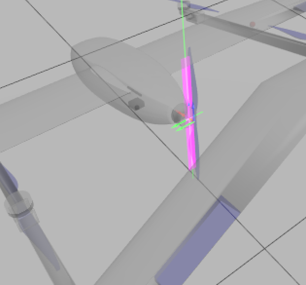
4. Visual Debugging (Pink Box) In View -> Inertia, the pusher’s inertia appears as a long stick (similar to standard_vtol). However, when the motor runs, it seems like the physics engine is trying to spin this “stick” sideways, causing extreme torque/gyroscopic effects.
5. My SDF Snippet (Current Attempt)
6. My Question When the Parent Link (base_link) is rotated 180 degrees:
-
Does the Child Link’s Inertia Matrix (
ixx,iyy,izz) need to be swapped/transformed manually? -
Why does the
standard_vtolconfiguration fail on a rotated frame? -
Should I use a Spherical Inertia (all axes equal) to avoid this issue, or is there a “correct” way to align the tensor?
(Attachments)
-
Screenshot: Inertia visualization (Pink Box).
-
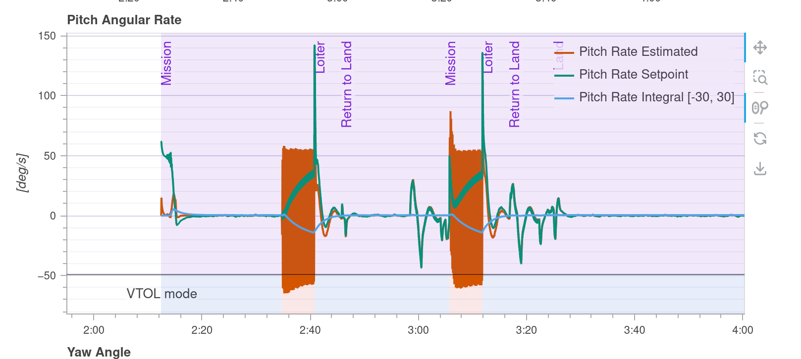
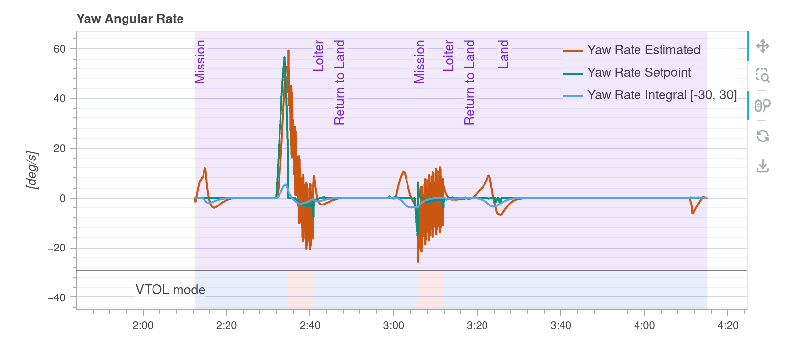
Log Graph: Yaw Rate & Acceleration spike upon pusher activation.
Any insights on Gazebo Inertia Frames with rotated parents would be life-saving!
watch YouTube: https://youtu.be/itXy3qR79Qg
<link name='rotor_puller'>
  <pose>0.714 0 0.025 0 0 3.14159</pose>
  <inertial>
    <pose>0 0 0 0 0 0</pose>
    <mass>0.019</mass>
    <inertia>
      <ixx>2.104e-04</ixx>
      <ixy>0</ixy>
      <ixz>0</ixz>
      <iyy>2.095e-04</iyy>
      <iyz>1.773e-06</iyz>
      <izz>9.887e-07</izz>
    </inertia>
  </inertial>
  <collision name='rotor_puller_collision'>
    <pose>0 0 0 0 1.5708 0</pose>
    <geometry>
      <cylinder>
        <length>0.02</length>
        <radius>0.22</radius>
      </cylinder>
    </geometry>
    <surface>
      <contact><ode /></contact>
      <friction><ode /></friction>
    </surface>
  </collision>
  <visual name='rotor_puller_visual'>
    <pose>-0.02 0 0 0 0 0</pose>
    <geometry>
      <mesh>
        <scale>0.001 0.001 0.001</scale>
        <uri>model://amsr_vtol/meshes/amsr_vtol_cruise_prop.dae</uri>
      </mesh>
    </geometry>
    <material>
      <ambient>0 0 1 1.0</ambient>
      <diffuse>0 0 1 1.0</diffuse>
    </material>
  </visual>
  <gravity>1</gravity>
  <velocity_decay />
  <self_collide>0</self_collide>
</link>

<joint name='rotor_puller_joint' type='revolute'>
  <pose>0 0 0 0 0 0</pose>
  <child>rotor_puller</child>
  <parent>base_link</parent>
  <axis>
    <xyz>1 0 0</xyz>
    <limit>
      <lower>-1e+16</lower>
      <upper>1e+16</upper>
    </limit>
    <dynamics>
      <spring_reference>0</spring_reference>
      <spring_stiffness>0</spring_stiffness>
    </dynamics>
  </axis>
</joint>
param set-default CA_ROTOR_COUNT 5
Rotor 0 (Motor 1): Front Right - CCW (
param set-default CA_ROTOR0_PX 0.3418 # (0.4305 - 0.0887) = +0.3418 (앞)
param set-default CA_ROTOR0_PY 0.502 # Y > 0 (오른쪽)
param set-default CA_ROTOR0_KM 0.05 # CCW
Rotor 1 (Motor 2): Rear Left - CCW
param set-default CA_ROTOR1_PX -0.3295 # (0.4305 - 0.760) = -0.3295 (뒤)
param set-default CA_ROTOR1_PY -0.502 # Y < 0 (왼쪽)
param set-default CA_ROTOR1_KM 0.05 # CCW (대각선 Motor 1과 동일)
Rotor 2 (Motor 3): Front Left - CW
param set-default CA_ROTOR2_PX 0.3418 # (0.4305 - 0.0887) = +0.3418 (앞)
param set-default CA_ROTOR2_PY -0.502 # Y < 0 (왼쪽)
param set-default CA_ROTOR2_KM -0.05 # CW
Rotor 3 (Motor 4): Rear Right - CW
param set-default CA_ROTOR3_PX -0.3295 # (0.4305 - 0.760) = -0.3295 (뒤)
param set-default CA_ROTOR3_PY 0.502 # Y > 0 (오른쪽)
param set-default CA_ROTOR3_KM -0.05 # CW (대각선 Motor 3와 동일)
Rotor 4 (Motor 5): Pusher Prop - Forward Thrust
param set-default CA_ROTOR4_PX -0.1835 # (0.4305 - 0.614) = -0.1835 (뒤)
param set-default CA_ROTOR4_PZ 0.0322 # (0.0572 - 0.025) = 0.0322 (아래)
param set-default CA_ROTOR4_AX 1.0
param set-default CA_ROTOR4_AY 0.0
param set-default CA_ROTOR4_AZ 0.0
param set-default CA_ROTOR4_KM 0.0