Hello everyone!
In order to lift my DSLR camera in the air, I decided to design a larger drone and build. So far, I have only experience with smaller fast quadcopter.
I always like to find difficult projects to grow around it, relative to my knowledge.
So the decision fell on a 12 engine machine.
For this I have already done some development work and milled a prototype.
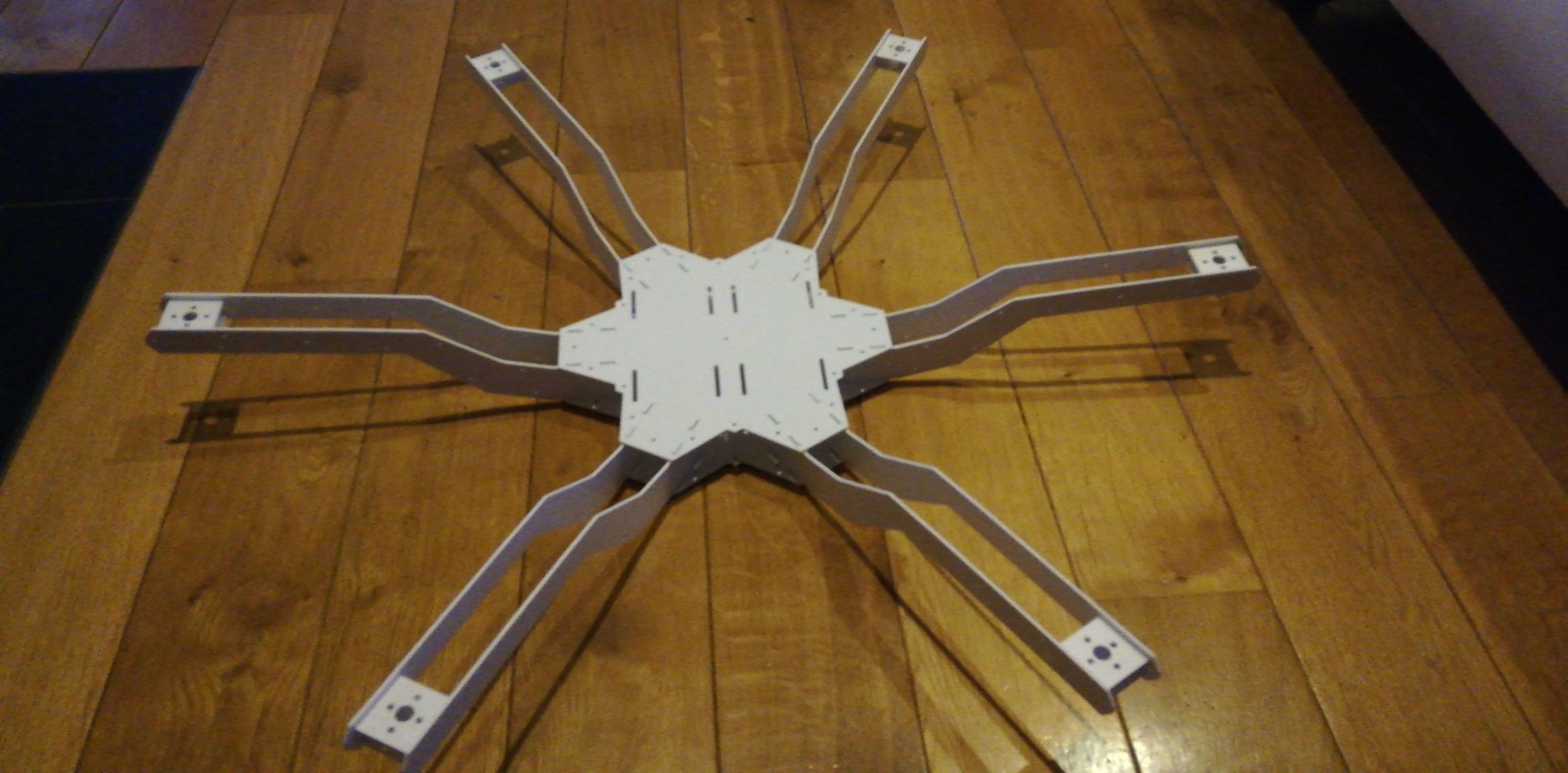
I’m currently planning with a Pixhawk 4 as FC. My frame design is designed for 9 inch propellers. In addition T-Motor AIR Gear 350 with 920 KV engines x 12 and 20A ESC’s.
According to my calculations, this should provide enough thrust to lift the weight of the drone + camera long enough, for my needs, in the air.
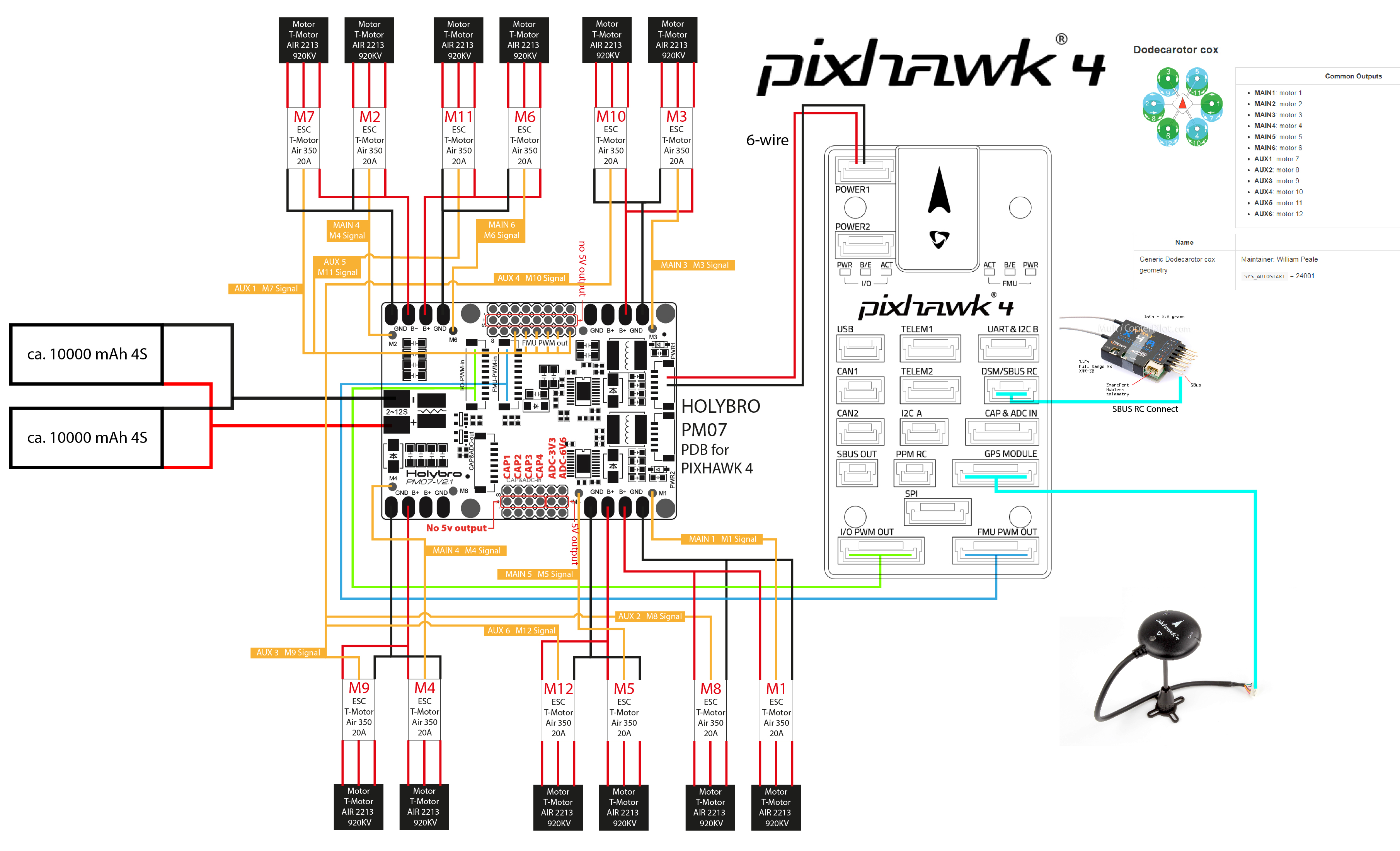
For me, the following points are currently to be clarified, to which I hope to get constructive answers here. I also attached a plan of the wiring, which is not my greatest strength.
-
I wonder how 12 motors are powered by the HOLYBRO PM07 PDB for PIXHAWK 4? For this I have an idea (see plan), but I do not know if I think everything right here. Can I realize the power supply of the 12 motors from only 6 connections?
-
The description of the HOLYBRO PM07 PDB for PIXHAWK 4 says “PCB Current: total 120A outputs (MAX)”. Is this the maximum ampere flow of an output for the engines? Or is it the maximum number for everything together. The latter would be surpassed by the engines at peak load (12 x 20A = 240A).
-
If the HOLYBRO PM07 PDB for PIXHAWK 4 is not useful in the context of the dodecarotor cox which PDB could I use? What options do I have to fully supply the engines?
-
The first 6 motors are supplied with a drive signal via the I / 0 PWM line. The other 6 motors are supplied with signals via the FMU PWM line. Unfortunately, I find no explanation for what FMU is the abbreviation, but would like to know.
I think I have more questions, but I would be happy to get answers and hints.
greetings
CHO