Hello all, I am looking for some advice on how I can control a servo over UART with a standard TELEM2 port on a pixhawk. Right now I have it all wired up and the servo TTL converter board is receiving TX from mavlink on my ModalAI Flight Core v2 FC. I am looking for any tips on how to go about programming a toggle switch on my transmitter to move the servo to a desired position. Would this be enabled via a custom module?
Hi.I think you can use one of these to do this.
If you can listening a mavlink message from your servo board rx you actually done most of the work I think. You only should start a mavlink stream on TELEM2 port. (Or any other uart). Basically you should follow these steps:
- Code something it will generate servo pwm commands
- Define a uorb topic and fill the fields with these datas.
3)Define a mavlink stream which generate mavlink packages by listening your defined uORB topic.
4)And add this stream to mavlink instance.
I think this is the most flexible way to do this because you can define everything according to your specific requirements. Second way you can directly use “RC_CHANNELS” mavlink stream.

When you enable Mavlink for TELEM2 port it will start share some mavlink messages including this. As you can see this mavlink message including all channel values of your transmitter. To sum up;
- Enable mavlink for telem2 port (MAV_0,MAV_1 etc.)
- Connect rx tx of telem2 port to your servo ttl and receive RC_CHANNEL mavlink message.(I’m not sure what type of board you’re using)
- It will directly gives you pwm value of all transmitter channels you can use these values to generate pwm commands.
If I misunderstood your problem please inform me. If this is the situation and you need more detail I can explain the steps with more detail ![]()
Hi, I really appreciate this explanation. I am using FEETECH bus servos in the STS lineup connected to a URT-1 board pictured here.


I dont think PWM works for this setup. These servos work off UART to TTL conversion through this board so the data that need to be sent to the board is via an SDK library they have for STM32/microcontrollers.
I was able to connect the board over USB to my desktop and send something simple with pyserial like:
import serial
import time

port = '/dev/ttyUSB1'
baudrate = 1000000

def calculate_checksum(data):
    return (~sum(data) & 0xFF)

try:
    ser = serial.Serial(port, baudrate, timeout=1)
    print(f"Opened port {port} at {baudrate} baud")

    # Servo command
    id = 0x03  # servo ID 3
    length = 0x09
    instruction = 0x03
    parameters = [0x2A, 0x00, 0x08, 0x00, 0x00, 0xE8, 0x03]  # Position = 2048, Speed = 1000
    checksum = calculate_checksum([id, length, instruction] + parameters)

    command = bytes([0xFF, 0xFF, id, length, instruction] + parameters + [checksum])
    print(f"Command to send: {command}")

    ser.write(command)
    print("Command sent")

    time.sleep(0.5)  # Wait for a response

    response = ser.read(64)  # buffer size
    if response:
        print(f"Received response: {response}")
    else:
        print("No response received")

    ser.close()
    print(f"Closed port {port}")

except Exception as e:
    print(f"Error: {e}")
This worked to move my servo to a desire position over usb from my desktop but I am unsure of how this would translate to the FC sending this command to over UART to the servo board. Would it still make sense to create a custom module in px4 that sends the position commands based on an RC switch?
Also here is a diagram of their example with an Arduino. Not sure why they have TX-TX and RX-RX but that seems to also work for seeing successful data transmission when connected to my FC that way too.

Here is the user guige and SDK Git for reference.
https://gitee.com/ftservo/FTServo_Python
Let me know if you have any suggestions ![]()
Hi. Naturally you can’t feed mavlink message to your board. It’is waiting for specific messages from MCU. So you should write your custom driver(module) to write to uart port. Adding a custom driver is possible. If you examine existing drivers especially which are using uart you can see the way. Basically there is no big difference than connecting an arduino to the servo board with uart.
In documents you can see basics of driver development:
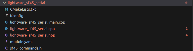
As document says best way is use a driver as template. I have written a few for unsupported sensors but I was only reading coming data. And I only followed tfmini lidar driver as template I only changed decoding part. As I see lightware_sf45_serial driver using uart port and including both read and write parts. Probably it can be a good point to start for you.(src/drivers/distance_sensor/)
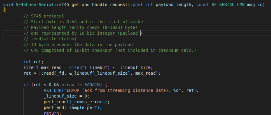
There is a reading part as you can see
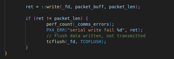
And also a writing part
Most of the part will not change. If you’re familiar with uart communication with mcu like stm32 you can implement this quickly. If you’re not familiar still it’s not so hard you can adapt an existing driver. In such cases using debug messages with PX4_INFO very helpful.
Second way:
If you hava a SBC like raspberry in your setup you can send mavlink data to it and handle it with a mavlink handler like MAVSDK. And do the same things like your servo board connected to your desktop.