Multi_tables.py generated scale tables

Hi everyone, I’ve been looking into the code behind specific air frame configurations, and the generated scaling values that make them “unique” to other crafts.

I stumbled upon the “multi_tables.py” script which generates the “mixer_multirotor.generated.h” file temporarily. From examining the code, I see that it generates a RollScale, pitchScale, yawScale and thrustScale for each motor on a craft, based on that motors angle from the front of the craft. I wanted to look into the numbers it generated, but I started confusing myself on what those numbers actually mean. I understand that the roll and pitch scales are generated by doing the cos of the angle (from the front of the craft), and the cos of the angle+90, but I’m confused as to why these numbers are correct.

Here’s how I’m looking at it.

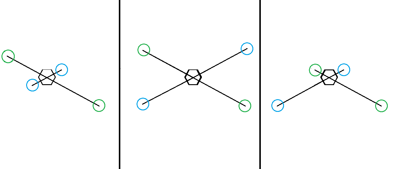
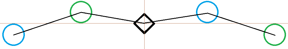
I’m imagining a craft that looks like this from a top down view… (obviously not perfectly to scale as far as the angles are concerned, but it should do)

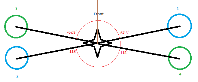
I input a craft called example_x into the “multi_tables.py script” like so,

example_x = [
[  67.5, CCW],
[ -115, CCW],
[  -67.5, CCW],
[  -115, CCW],
]

and it generates this corresponding output to the “mixer_multirotor.generated.h” file

const MultirotorMixer::Rotor _config_example_x[] = {
	{ -0.923880,  0.382683,  1.000000,  1.000000 }, #motor 1
	{  0.906308, -0.422618,  1.000000,  1.000000 }, #motor 2
	{  0.923880,  0.382683, -1.000000,  1.000000 }, #motor 3
	{ -0.906308, -0.422618, -1.000000,  1.000000 }, #motor 4
};
     #    ^           ^          ^          ^
     #RollScale, pitchScale,  yawScale   thrustScale

I’m confused as to why the roll scale is higher than the pitch scale. Shouldn’t it be that when the motors are interacting in a roll the forces are “further out” out from the center of gravity, and thus have more leverage to take advantage of, requiring less of a change in thrust to execute the roll?

The only thing that makes me question MY thought process, is that the “further out” roll interaction needs to lift the motors physically further than the “shorter” pitch interaction. This being because the arc-length they must travel to transfer an equal amount of propeller force inwards towards the craft is much longer than that of the the pitch.

These are my two theories on where the scaling values are coming from, my gut tells me the first one should be right, but the data seems to favor the second theory.

I’d love if someone could let me know which theory is correct, (or if they’re both wrong)!

Thanks in advance,

Vergil-SI

2 Likes

I don’t fully understand this myself, but I’d like to.

If you assume each arm is the same length, then the front motors (at ±67.5 degrees) are further from the roll axis and therefore have to travel further for the same roll. Similarly for pitch the front motors are closer to the pitch axis.

What I’m not entirely sure of is how to handle the arms being different lengths, or motors being different sizes. If you look at the deadcat mixer (https://github.com/PX4/Firmware/blob/master/src/modules/systemlib/mixer/multi_tables.py#L79) there’s an optional thrust scale.

The more I’ve thought about it, the more I think I agree with my second theory, which is the same as what you’ve said. It would seem that the arclength that the far edges of the craft needs to move matters far more than the whole “leverage is more the further from the rotational axis” theory.

My next thought was actually the same as yours as well. It doesn’t seem right to me that all three of these quads below would have the same values just because their angles are the same.

Our “further arclength travel” theory gets kind of obliterated here.

I’m particularly interested in my furthest right example, as I’d like to look into a design for a craft that would look something like this below.

In my example, I’ve made sure the motors are equidistant from the pitch axis which simplifies things for pitching purposes, but I worry about the repercussions of the roll when the the motors aren’t all 4 equidistant from the roll axis.

Any thoughts?

edit I forgot to mention what you said about the thrust scale. I noticed it and think that could be useful (especially in my furthest left example), however on a craft like the one I’m looking into, it seems like we run into the same kind of problem with things being wonky due to different distances from the CG. If I wanted to add extra thrust to the outer motors in relation to a roll… It would throw off the pitch.

2 Likes

It is a good question, based on the dynamic model of quadrotors, torques induced by propellers make the change in attitude of the drone no matter what the arc length of propeller movement will be. So your first theory should be correct, the further from the axis of rotation, the more the torque is higher, then scale value must be smaller if it is used to calculate propeller rotation speed.

I am also interested in this problem, it would be good to have a response from developer contributors. @LorenzMeier

You can compute the mixer matrix as follows:

Write down the moment about each axis as a function of motor commands. Additionally write down an equation for desired thrust which is simply the sum of all motor commands.
Then you end up with something like

Moments_and_thrust = A * motor_commands

where

Moments_and_thrust is a vector with the 3 body moments and the desired thrust
A is 4 x num_motors matrix
motor_commands is what you actually want to find out

You can now compute the inverse of A (or the pseudo-inverse if you have more motors than equations) to obtain the mixer matrix. Lastly, you will have to scale the columns to bring it to a desired normalized range.
This technique also allows you to have motors at different distances to the CG which will result in different thrust factors.

I’m having trouble understanding your response in general. Are you saying that this matrix

const MultirotorMixer::Rotor _config_example_x[] = {
	{ -0.923880,  0.382683,  1.000000,  1.000000 },
	{  0.906308, -0.422618,  1.000000,  1.000000 }, 
	{  0.923880,  0.382683, -1.000000,  1.000000 }, 
	{ -0.906308, -0.422618, -1.000000,  1.000000 }, 
};

is calculated using all that math? or that it is just the A value in that equation. (All I know is that the above matrix is calculated using cos(angle) for pitch, and cos(angle+90) for roll.)

Sorry if I’m not understanding, but I’ve looked at your post for quite awhile and am confused as to what you’re calling the mixer matrix. If you have the time, could you spare an example? Math is always difficult for me to comprehend in a forum post environment without some sort of small example for me to connect the typed out variables with numbers…

That is my exact question. When it is calculated the inverse of the matrix as this script seems to calculate the A matrix.
Then in ‘mixer_multirotor.cpp’ , for exemple, it is used to calculate the motor_commands. Am I wrong?

I suggest you to read a paper about quadrotor dynamics and control, most of them explain how this matrix is defined.
Briefly, roll and pitch movements are result of moments generated by the propeller’s thrust force on each axis (X and Y respectively).

For exemple :
Roll moment = force_motor1distance1_to_x_axis + … + force_motorNdistanceN_to_x_axis (remember to consider direction of rotation).

Here cos(angle) calculates the distance to the Y axis and cos(angle+90) = -sin(angle) calculates the distance to the X axis assuming that the arm lenght is 1.