Gentleman,
I’m new to the drone world (noob), just started experiments for educational purpose with Pixhawk 2.4.8 (Chinese Clone). I accidently checked the upgrade bootloader parameter while flashing it using QGC (mac).
Now when I connect it to QGC again its not flashing it anymore. The flashing process fails, I tried using different USB cable, different computer (windows 10 with Mission Planner) etc. but no luck so far.
I know that the bootloader can be flashed using a hex file to bring the board back to normal. How to boot it in DFU mode as there are no boot0 pins as such on the pixhawk 2.4.8 clone? Any help or guidance please. Thank you!!!
One thing you can try is using a JTAG tool to connect your pixhawk on the debug port, which shall locate at the opposite side of the USB port. There is an “official” tool called Dronecode Probe or if you have a JTAG/SWD programmer, you can use that tool.
Take a look at this as a reference:
Thank you for your response.
I’m curious to know more about the JTAG tool and how to connect it to the pixhawk board? a detailed document is needed for me as a new user.
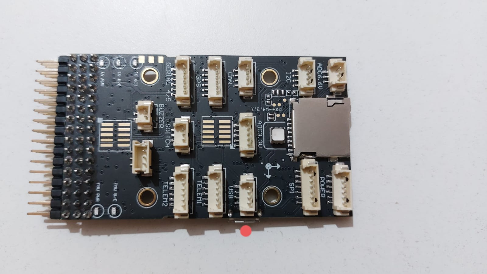
I’ve attached a pic of my pixhawk board, could you please confirm the port which is opposite side of the USB port on this board (marked with a red dot)?
I’m searching online about this JTAG tool and I see there many different types and I’m confused which one to buy. Any reference image of the JATG tool please? so that don’t end-up buying something irrelevant.
Hi. Sorry I made a mistake about the position of the JTAG port.
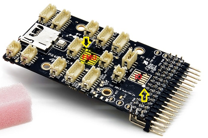
I never get in touch with this version of pixhawk, but I guess it’s similar as the 3DR Pixhawk1, which you can find the reference from here: Redirecting to latest version of document (main).
If you go the the bottom part of the link, in the SWD port part, you will find that the JTAG ports are actually those two bare solder pads. In your case since you messed up the bootloader, so you may try with the FMU port, which is the one in the middle.
The bad thing is you have to find a connector and solder it by yourself. Since it is a surface mounted type solder pad, it’s not so easy for beginners. I suggest to find someone with more solder experience to help you if you never did this.
Regarding the JTAG tool, as I said in the last reply, I used the Dronecode Probe since it comes with the cable that can connect to most pixhawks easily. However in your case you need to solder the connector by yourself so it really depends on you.
Here I uploaded the image of the 3DR pixhawk, and the two yellow arrows are pointing to the JTAG ports. As I said you may want to connect to the FMU one.
@hitagisol Thank you for the guidance and thank you for sharing those links.
I do have a little experience about soldering wires while building a quadcopter. I think I can give it a try with that FMU pad.
I looked at that JTAG adapter and I see multiple colorful output wires on the adapter. Could you guide which color wire to solder at which particular pins on the FMU pad.
I looked at the pin output diagram and got confused about which JTAG wires I need to solder on the FMU pad (10 flat pins at the middle of the board). I’ve attached here the JTAG adapter colorful wires and the FMU pins diagram for reference.
@hitagisol Thank you so much!
I’ll buy one JTAG/SWD adapter and try it out. It will take some time to get it delivered (probably next year!! 2022). I’ll update here on this thread about the status once I try it out.
Merry Christmas !!!
@hitagisol Happy new year!!
I managed to fix the pixhawk board and now its back to normal.
I used this tool called ST-Link V2 programmer (attached image) to flash the bootloader and it worked like charm. However, soldering the wires onto the Pixhawk FMU pad is very difficult due to the tiny little flat pins on the board.
Now I can flash the firmware and calibrate it using QGC (Windows 10), but every time I connect the pixhawk board to QGC via USB, I get an error that “Compass 1 is not found.”. I did calibrate the compass multiple times and the calibration is successful, but not sure about the error. Any clue please?
Hi @DM1. Happy new year!
it’s so nice to hear that you fix the problem!!
Regarding the compass error, if I remembered well, the internal compass is set to compass 0 by default so the compass 1 shall refer to the external one (like the one in the GPS module). So it’s not surprise that it can not find compass 1 if you did not plug in that.
Otherwise, if you only want to use the internal compass, there is a parameter you can try to modify. Depending on which version of firmware you are using, it could be " CAL_MAG1_PRIO" or " CAL_MAG1_EN".
Hi @Numecon
This is what I followed and it worked…
So first, on the ST-Link device, you need to connect four wires to the individual pins (any color wire), like this…
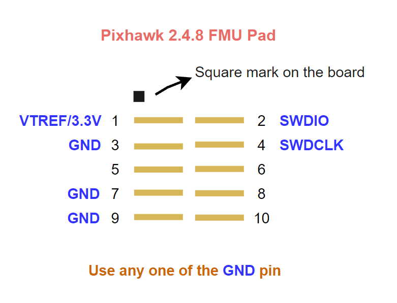
SWDIO
SWCLK
VTREF(3.3v)
GND
you can find these 4 pin names on the ST-Link device very easily, atleast in my case the pin names are mentioned on top of the device so very easy to locate (see pictures above).
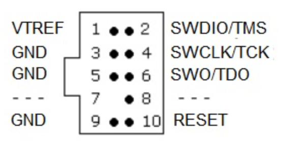
After that, on the Pixhawk board’s FMU pad (screenshots are above), you can see 10 little flat pins lined up and there is a very small square mark on one of the corners of those flat pins, that’s the pin 1.
Once you identify the pin 1, then follow this screenshot below to solder those 4 ST-Link wires onto the FMU pad. Good luck with soldering!
Hope it helps!
Phew!!.. This post and several hours of other reading helped me fix the bootloader and unbrick a PX4 FC that i was installing for a friend… the pin-out picture above and the tip of using an ST-LINK was super helpful… to add to this for the next person i will say that i was able to write the bootloader/FW.hex with the STLINK connected to the JTag contacts shown in the image, and the “STM32CubeProgrammer” software…
BIG Thanks to the community!!
+1, props to @DM1 for sharing this fix. I was able to somehow solder leads on those tiny af pads using the ST-Link V2 programmer. J-flash wasn’t working, ended up writing the bootloader using the STM32 St-link Utility making this a Great Success.

 2022). I’ll update here on this thread about the status once I try it out.