In multi-sensor fusion systems, coordinated perception between cameras and radar has become critical for environmental understanding. Cameras identify object categories by capturing texture information, whereas radar utilizes laser or millimeter-wave technology for precise all-weather distance measurements. Fusion of data from these two sensors effectively overcomes the shortcomings of single-sensor approaches (e.g., camera susceptibility to lighting conditions, radar lacking semantic information), greatly enhancing the stability and accuracy of dynamic obstacle tracking.
Application Scenarios
Autonomous Driving
In autonomous driving, cameras collect visual environmental information for classifying and identifying pedestrians, vehicles, and traffic signs, while radar provides high-precision distance and velocity measurements to avoid misclassification (such as distinguishing road signs from real obstacles).
Robotics
Ground robots use radar to detect distances to obstacles in real-time and cameras to identify obstacle types. Aerial drones employ radar for measuring altitude and cameras for recognizing landing platform markers (such as QR codes), achieving precise landings.
Localization and Mapping
Laser SLAM generates a 3D contour map of the environment, and in combination with semantic landmarks provided by cameras, it offers stable support for high-precision localization and path planning.
Importance of Time Synchronization
Multi-sensor fusion technology is widely applied in the field of SLAM (Simultaneous Localization and Mapping). Ensuring synchronization of sensor data is key to enhancing system robustness and accuracy. Due to differences in sampling frequency, startup latency, and data transmission between cameras and radar, ineffective time alignment may lead to data fusion errors, impacting system performance. Thus, resolving time synchronization between sensors is critical for designing camera-radar fusion systems to achieve accurate environmental perception and localization.
Common Time Synchronization Methods
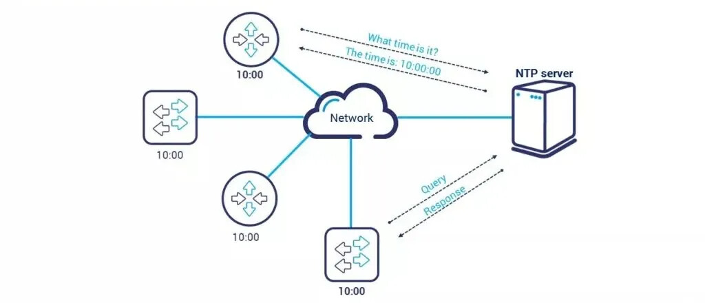
NTP (Network Time Protocol)
NTP synchronizes system time through network servers, generally achieving millisecond-level precision, suitable for low precision requirements. It is easy to deploy but susceptible to network latency, widely used in servers, industrial devices, and robotics.
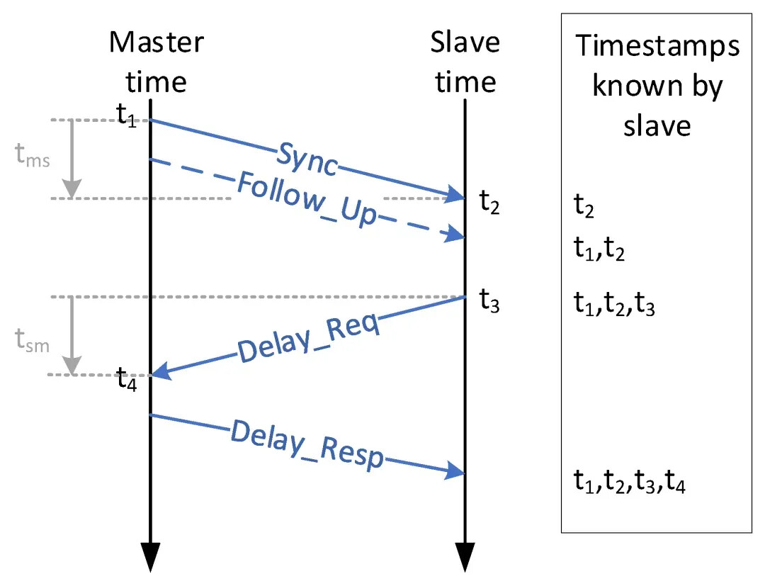
PTP (Precision Time Protocol, IEEE 1588)
PTP provides high-precision time synchronization, primarily used in local area networks (LAN) to achieve nanosecond-level synchronization. Its core principle relies on master-slave architecture and bidirectional message exchanges to measure and compensate network delays for device clock alignment.
GPS Time Synchronization
GPS receivers output PPS signals strictly aligned with UTC seconds pulses. Other devices capture PPS rising edges via hardware interfaces (GPIO, TTL) and use this hardware pulse as a time reference to correct local clocks or triggers.
Hardware Trigger Synchronization
Dedicated triggers or FPGA/MCU generate unified physical trigger pulses (e.g., TTL low/high-level signals). All devices simultaneously acquire data frames, with timestamps directly generated by hardware.
How to Test Camera-Radar Synchronization?
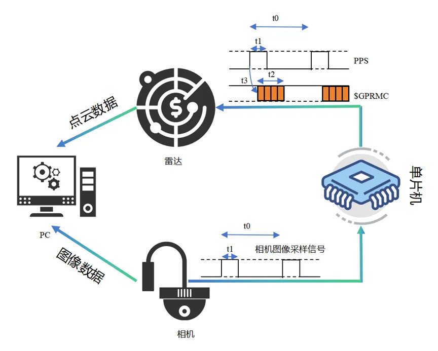
Taking a four-camera system and Livox Mid-360 LiDAR as an example, we first test whether camera and radar data timestamps remain consistently synchronized within a stable range.
Synchronization Method
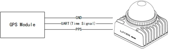
According to radar and camera specifications, both devices support hardware synchronization. Radar synchronization utilizes UART with specific pin signal requirements. To simultaneously meet radar and camera hardware triggering, STM32 microcontroller generates pulse signals.
Testing Steps
-
Configure camera for equal-interval sampling, producing pulses received by STM32 and converted into 1Hz synchronization signals (1PPS).
-
STM32 configures radar and camera hardware triggering requirements, connecting corresponding pins to radar and camera hardware trigger ports.
-
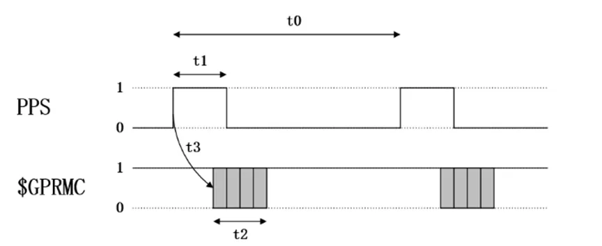
The test trigger frequency is 10Hz; intervals are defined by t0 (interval between consecutive rising edges of second pulses), t1 (high-level duration of second pulse), t2 (GPRMC transmission time), and t3 (GPRMC data transmission delay relative to pulse rising edge).
Testing Results
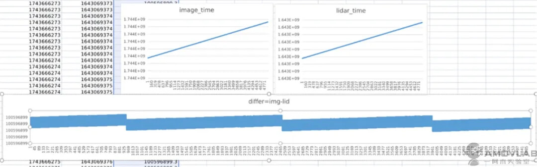
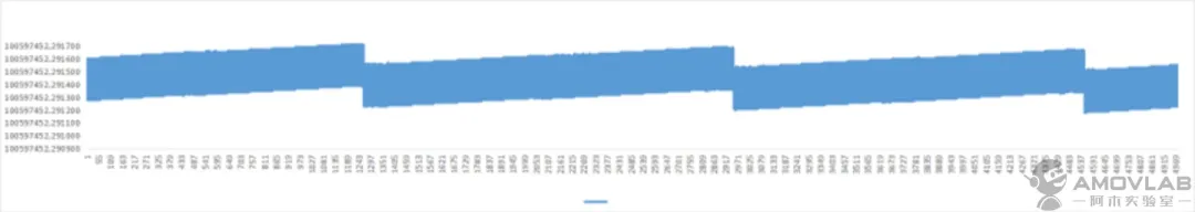
A test demo records timestamps of each frame from radar and camera, assessing synchronization success by analyzing convergence of their timestamp differences in UTC format.
Results show consistent convergence (Fig. a), with differences always under 1ms (Fig. b), indicating successful radar-camera synchronization.