Hi!
I’m developing my Master’s Thesis, and I’m using the PX4 toolbox in Simulink to design a customized controller for a quadcopter. I want to apply a model design approach, so I want to create the controller in Simulink and then through code generation, I want to perform SITL, PIL and HIL on Gazebo in order to validate my controller and then deploy the generated code on the real drone.
I’m having problems with the simulator I want to use.
Does anyone know how to perform SITL in Gazebo using the PX4 Toolbox in Simulink? I have just two simulators listed on the settings (jMAVsim and Simulink), how can I run my Simulink model on Gazebo?
In my opinion if you want to develop using the UAV toolbox in MATLAB then it’s probably best to stick to that system and do the simulation there. I’m not sure how you could also get the Gazebo simulation in the mix as you would eventually have two simulators.
So do you think is not possible to use Gazebo as simulator with the PX4 toolbox? I want to use gazebo as the unique simulator. I want to use Simulink and the px4 toolbox just because they allow me to design the controller (model based design approach), simulate it and flesh it on the real target. On Simulink in the PX4 toolbox settings, there are 2 different simulators we can choose: jMAVsim and Simulink. I don’t want to use these two simulators, but I want to use Gazebo because it is more realistic than the others.
Is it not possible to use this toolchain?
Hi Matteo,
I was able to connect the PX4 SITL ROS2-Gazebo to my Simulink model through Simulink’s ROS Toolbox.
You can use the new XRCE-DDS configuration, this will allow you to see ros2 topics in your Simulink model and send/receive data from the PX4, finally implement a controller using angular velocity setpoints to send sendpoints for the rates + thrust.
However, you cannot generate the controller’s code directly to the PX4. You might have to use something like a companion computer running ROS2 + PX4 in OFFBOARD mode to send the rates + thrust setpoints generated by the custom controller, though there might be high latency in this method.
I have been working with a similar method for my guidance algorithms and it’s working smoothly in SITL, HITL, and on my real drone (although the guidance rates are much less than the control rates).
I’m building a Simulink simulation which includes the full control and estimation architecture of the PX4, if you have time you are welcome to join the effort ![]() .
.
Thank you so much for your help, I really appreciate it. Do you have the Simulink model though which you were able to connect PX4 SITL ROS2-Gazebo with Simulink using ROS toolbox? Do you have a step-by-step procedure through which I can learn this toolchain? How does it work? You build your Simulink model using the ROS Toolbox and you run it in the OFFBOARD mode on PX4?
Sorry, I’m not an expert, and I’m trying to learn how this toolchain works.
You can use the ros2/subscribe or ros2/publish Simulink blocks to send/receive data from the PX4.
I did a small test with the following procedure:
-
Follow this guide for the PX4 - ROS2 offboard setup. This is a great guide that explains how to set up all the simulation environments.
-
You can create a launch file to launch only the PX4 Gazebo SITL and the micro_ros_agent.
-
In Matlab, generate custom ros2 message from the px4_msgs library.
-
Now, set your Simulink model to
Stop Timeinfand setSimulation Pacingto1. (note that there isn’t hard sync between the Simulink model and the Gazebo simulation, we assume that it’s running “fast enough”). -
Create your control/guidance model in Simulink, inputs/outputs from ros2 pub/sub blocks.
-
Run the launch file and the Simulink model.
The communication between the Simulink model and the PX4 SITL - Gazebo is based on ros2.
In terms of code generation, you can do one of the following:
-
generate a ros2 node directly from the Simulink model. It will create a ros2 package with the model’s node in C++.
-
generate c++ class from the control model, then wrap the c++ class with your own ros2 node. You can use the
setExternalInputs,step,getExternalOutputfunctions generated by the code generation.
After you export the model from Simulink you can copy the package to the companion computer workspace (assuming that it has ros2 installed).
Hello,
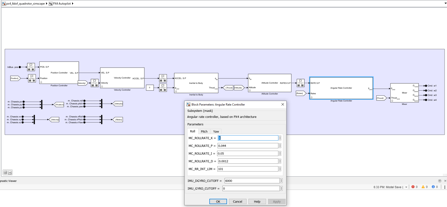
My name is Kipyo Park, and I am currently a master’s student. I would like to explain what I am trying to do and ask you a few questions. I am using Ubuntu 20.04 and PX4. I want to obtain the setpoint delta from the mc_* controllers in PX4, as found in PX4-Autopilot/src/modules at main · PX4/PX4-Autopilot · GitHub. However, modifying the PX4 code seems challenging for an amateur like me, so I am considering implementing the PX4 controller in Simulink.
While researching, I came across your GitHub repository: GitHub - iftahnaf/px4_simulink_simulator: Simulink models of UAV's with PX4 control system architecture.
From what I can see, it looks like you are attempting to implement the PX4 controller in Simulink. However, the Simulink model does not seem to run. Is it still a work in progress?
Additionally, I am currently using ROS1, but it seems from your responses that you are using ROS2. Does this mean it won’t work with ROS1?
Thank you for your time and assistance.