About
After the posting of Which USART ports are connected to which TELEM ports - #2 by junwoo0914, I continued on a quest to understand how exactly the target board configuration files are structured, and here’s what I found (rough summary):
Note, all the folders related to the target are relative to the target directory (e.g. “boards/matek/h743-mini”) here: PX4-Autopilot/boards/matek/h743 at main · PX4/PX4-Autopilot · GitHub
Also, there are quite nice documentation on this topic, so you can check them out too:
- Flight Controller Porting Guide | PX4 Guide (main)
- Manufacturer's PX4 Board Support Guide | PX4 Guide (main)
- NuttX Board Porting Guide | PX4 Guide (main)
PX4 level configuration
Here are all the high-level PX4 related configuration files.
default.px4board
- Maps the “/dev/ttySx” NuttX ports to the appropriate PX4 conceptual Telem, GPS, Radio, etc ports
- Configures which module / drivers to include (e.g. DSHOT, Control Allocator, etc)
NuttX level configuration
All the low level NuttX related configuration files.
nuttx-config/nsh/defconfig
- Configures which USART, SPI, I2C, etc instances are configured to be used (e.g. You can either select to use certain pins as USART RX/TX, or as a PWM output)
- Sets which USART port will be used for the debug console
- Sets up various other basic NuttX configurations (e.g. Watchdog, RAM size, etc)
Mix of both PX4 and NuttX configurations
And we finally have the biggest chunk of all, the .h and .c files that lies at the intersection of configuring PX4 and NuttX.
src/board_config.h
This defines overall “board spec” that a hardware manufacturer would outline, such as how many PWM channels there are, where the RC input is connected (to USART port), etc.
src/hw_config.h
This seems to set more hardware configuration, especially including which “/dev/ttySx” port will be used for the debug console:
src/timer_config.cpp
One of the most interesting files. It defines which Timer gets associated with which DMA (not sure exactly how they are determined).
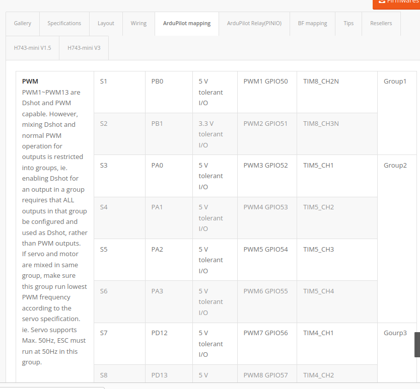
As well as setting up the array “timer_io_channels” that defines all the PWM/DSHOT/ONESHOT/etc related (all the motor/servo control interfaces) pins in order.
So this perfectly matches the “DIRECT_PWM_OUTPUT_CHANNELS” set in src/board_config.h above for the MATEKH743 target’s case. And this order defines which IO pin is PWM 1, 2, etc.
You can actually verify in manufacturer’s website that the list above matches the PWM port pin assignments (and timer setups), like below
src/i2c.cpp
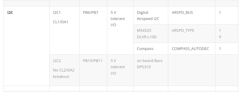
This file defines which I2C busses there are, and whether they are internal or external.
For this case too, the manufacturer’s specification on I2C1 being external (breakout board connection), and I2C being internal matches with the configuration.
src/spi.cpp
This defines the SPI devices and instances.
This was not listed on the manufacturer’s website, but I am guessing that SPI1 and SPI4 are used for IMU sensors, and SPI3 for external SPI connections (e.g. telemetry radio), and SPI2 as OSD module connection.
src/init.c
This defines the initial startup and reset functions, as they may differ for different targets.
For example, the board_app_initialize function is implemented, which is the standard NuttX function that must be implemented by the user, to handle the initialization phase.
You can find the definition of this function in NuttX side here:
Some other fun facts 
So aside from the details above, here are more in-depth details that I found quite interesting!
NuttX IO timer channel setting
I was curious what the “initIOTimerChannelMapping” function from " src/timer_config.cpp" actually does, which supposedly registers the timer setting for the PWM drivers.
The implementation lives within PX4 under “platforms/nuttx/src/px4/common/include/px4_platform/io_timer_init.h”, and it supposedly configures the timers to be usable by the PWM drivers!
PWM driver in NuttX level and PX4 level
There are implementations which exposes simpler functions to actually command the values for the PWM pins from the PX4 driver stage.
For example, here:
This function gets used in turn in the PX4’s pwm driver side like here:
I found it quite interesting how there’s the 2 separated layers (even after NuttX level definitions of PWM output pins in “timer_config.cpp”!) ![]()
You can find other low-level implementation of the drivers in this folder: PX4-Autopilot/platforms/nuttx/src/px4/stm/stm32_common at main · PX4/PX4-Autopilot · GitHub
FYI, it’s also quite interesting to read the logic behind board revision number detection mechanism like here: PX4-Autopilot/platforms/nuttx/src/px4/stm/stm32_common/board_hw_info/board_hw_rev_ver.c at 56b59dc1551fb6c3976b4b69b108d369cb6aa267 · PX4/PX4-Autopilot · GitHub
nuttx-config/bootloader/defconfig
In the bootloader defconfig, you will find some interesting things, including the entrypoint for the bootloader code itself.
And this of course corresponds to the name of the bootloader code inside the target folder: