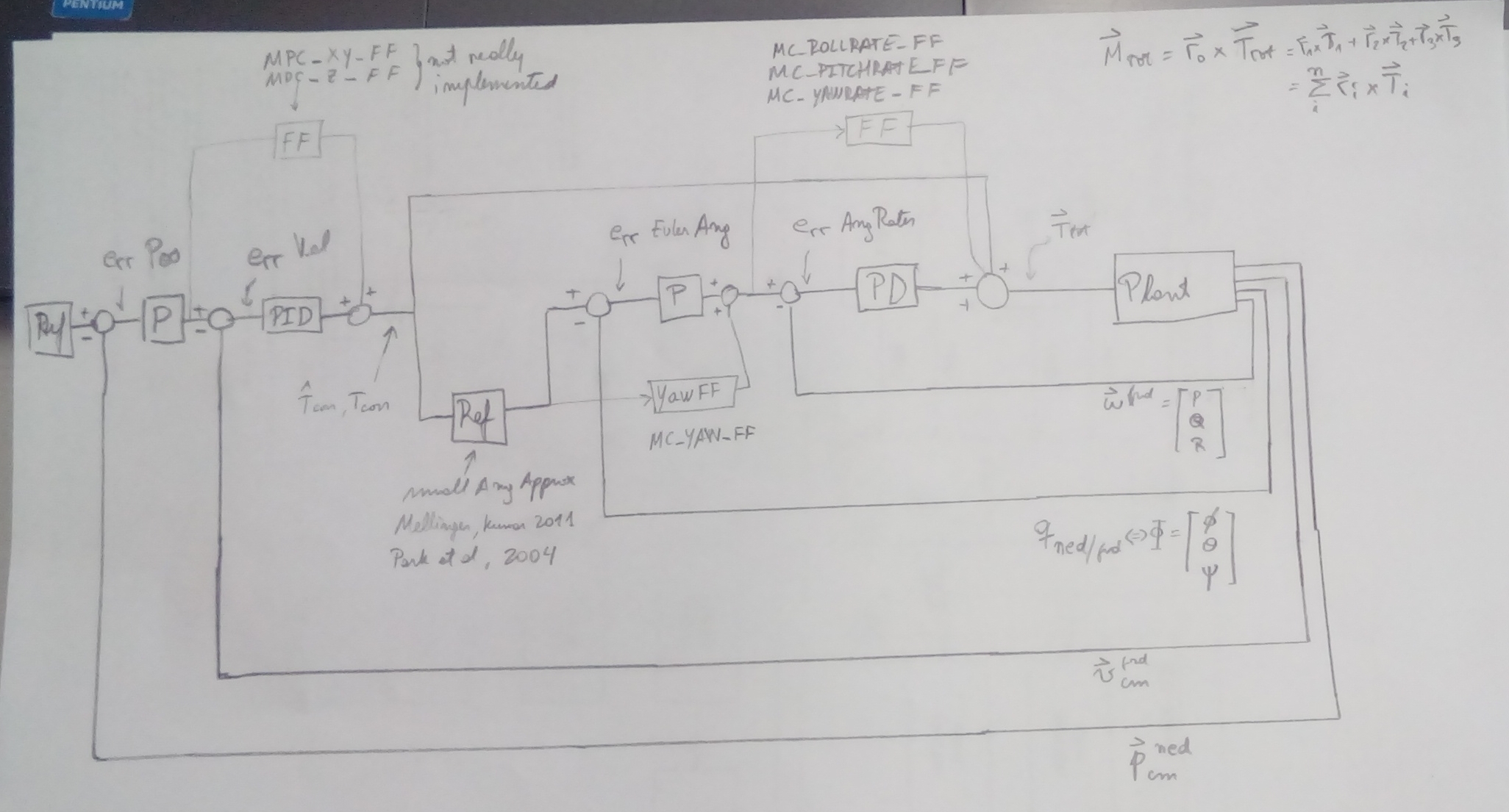
I have been searching in Library has been merged into the PX4 User Guide and the web in general for a complete control loop architecture of the px4 without much success. So, I started looking at the source code, specially the mc_att_control_main.cpp and mc_pos_control_main.cpp files, and I came up with this.
So, I know that there are many scale factors not being shown. But, is this the control loop architecture implemented in the px4 source code for a quadcopter in stable flight?
Nice been looking for a diagram like that. From reading through the source the control algorithms are from this paper,
Mellinger, Daniel, and Vijay Kumar. “Minimum snap trajectory generation and control for quadrotors.” Robotics and Automation (ICRA), 2011 IEEE International Conference on. IEEE, 2011.
Any idea how close those algorithms are implemented in PX4? I’d like to use that as a benchmark for our own development.
I remember reading in the source code the same comments about that paper.
Apparently they “wanted to” use that algorithm. But is not currently implemented.
@Paul_Riseborough@LorenzMeier Can you please confirm or comment on the control architecture diagram posted by the OP here? That would be of great help.
Thanks!
Just be careful that the inner controllers (rate controllers) for position and angle are implemented with a PI+D structure, which means that the derivative component is not the related to the angular rates errors e(t), but to the plant output itself y(t).
I would say something like
u(t) = kp e(t) + ki int e(t) dt - kd d(y(t))/dt
Moreover, I would say that angular rates are controlled using a full PID controller.
@alexh
“inner controllers (rate controllers) for position and angle are implemented with a PI+D structure”
and
“Moreover, I would say that angular rates are controlled using a full PID controller”
statements seem contradictory to me. Can you please elaborate?
Thanks!
The original diagram shows that angular rates controllers are PD controllers, however, gains like MC_PITCHRATE_I suggest that they use a PID structures.
Although I called it PID controllers, they are implemented using a PI+D structure, as I stated above.
You were right that I missed the integral term, but I found something different to what you said. Because the integral term is defined in a weird way.
Line 1070
    // Perform the integration using a first order method and do not propaate the result if out of range or invalid
    float rate_i = _rates_int(i) + _params.rate_i(i) * rates_err(i) * dt;
So, in a nutshell to me it seems like
Proportional element defined as usual
Pgain * Perror
Second element (defined as such in lines 1071 - 1074) is quite Sui generis
Ierror + Igain * Perror
Third element is again defined as usual (although derivatives are low-pass filtered)
From a theoretical point of view, let ui(k) be the integral term and e(k) the rate error at instant k, respectively, (represent by rate_i and rates_err in the code), let Ui(z) and E(z) be their z transforms, if implemented as you mentioned (the recursive definition that you called a “weird way”), we can apply the z transform to the formula
ui(k) = ui(k-1) + ki * dt * e(k)
to find out its transfer function
Ui(z)/E(z) = ki * dt * / (1 - z^(-1))
and that’s the same expression that is presented in the document that I mentioned.
So, in line with what you just said that there is nothing weird with the Integral gain.
Do we all agree then that the implementation is a PID + FF scheme ?
@mjtaheri, @toopazo
This is what I understood about the entire position/attitude control schematics of PX4 so far.
Please correct me if anything is wrong or missing.
As @alexh mentioned PID is compromised of PI+D [quote=“alexh, post:6, topic:3114”]
for position and angle are implemented with a PI+D structure, which means that the derivative component is not the related to the angular rates errors e(t)
[/quote]
Hi, I hope you made a progress in your project
I just want to make sure if you have validated your control architecture as we are trying to implement it in Simulink to tune the controller in a simulation… Are there other issues than the IP+D problems in the position and attitude loops?