No.5:Quadcopter Test Flight Experiment Based on RflySim
This experiment involves the construction of a quadcopter flight controller in MATLAB/Simulink. Control commands are transmitted through Simulink to control the attitude of the quadcopter on the platform. Proficiency in MAVLink communication and the tuning of parameters for quadcopter attitude control is essential.
The key content is divided into two parts: MAVLink communication and controller design. In this experiment, the MAVLink protocol is used for communication between the flight controller and the upper computer. On one hand, control commands sent by MATLAB are transmitted to the flight controller through the MAVLink protocol. On the other hand, the flight controller sends key status information to MATLAB for display through the MAVLink protocol, facilitating debugging and analysis. The controller adopts the classical PID controller, and to ensure the safety of the controller, it is necessary to limit the calculation results of each channel.
MAVLink (Micro Air Vehicle Link) is a communication protocol for small unmanned vehicles, first released in 2009. This protocol is widely used for communication between Ground Control Stations (GCS) and unmanned vehicles, as well as for internal communication between onboard computers and Pixhawk on vehicles. The protocol defines the rules for parameter transmission in the form of a message library. MAVLink protocol supports various vehicles such as unmanned fixed-wing aircraft, unmanned rotorcraft, unmanned vehicles, and more.
The controller adopts the widely used PID controller. The PID control algorithm consists of Proportional (P), Integral (I), and Derivative (D) components. PID control involves using the sum of the proportional, integral, and derivative of the variable deviation as the control input, calculating the output value as a control method. The structure diagram of a traditional PID control system is shown in the figure.
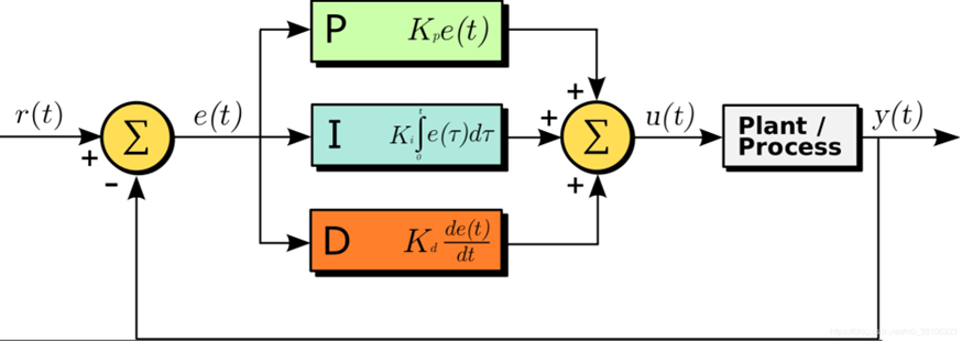
The proportional ‘P’ parameter in the figure plays a role in correcting deviations. A larger P parameter increases sensitivity to errors, resulting in faster error correction and quicker system response. However, an excessively large P parameter can lead to significant overshooting. The integral ‘I’ parameter contributes to improving accuracy; a larger I value leads to smaller tracking errors, resulting in more precise system tracking. The derivative ‘D’ parameter helps suppress overshooting by reflecting the rate of change of the error signal. It can decelerate the system when tracking is close to the desired target, and generally, the D parameter is not set too high, as an excessively large D parameter can cause system oscillations.
The PID control algorithm is widely used due to its simple structure, good stability, high reliability, and convenient tuning, making it a major technology in industrial control. Its main advantage lies in not requiring system modeling or identification. Once designed, it can be fine-tuned through experimentation. For general unmanned systems, which can be complex to model, the PID control algorithm is frequently employed.

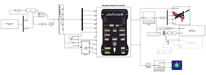
The overall framework of this experiment is illustrated in the diagram above. The MATLAB controller is designed using the PSP toolbox on the upper computer. The MATLAB controller can be compiled directly into a Simulink APP that can be used on the flight controller. By burning the Simulink APP into the flight controller, the controller can compute control laws and manipulate the unmanned aircraft on the platform. On the upper computer, the Simulink environment can be used to read the state of the flight controller or send control commands to it. The physical connection between the upper computer and the flight controller can be established via telemetry or USB. While telemetry connection has a slower communication rate, rendering some messages unavailable, a USB connection offers a higher communication speed, enabling the display of all information.
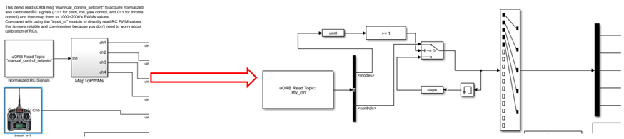
After performing hardware-in-the-loop simulation on the designed model, testing on the platform is necessary before actual flight. The input to the hardware-in-the-loop simulation model is replaced with the uORB message named ‘rfly_ctrl,’ a custom message in the RflySim platform. After burning this configuration, MAVLink protocol is utilized for communication between the flight controller and the upper computer.
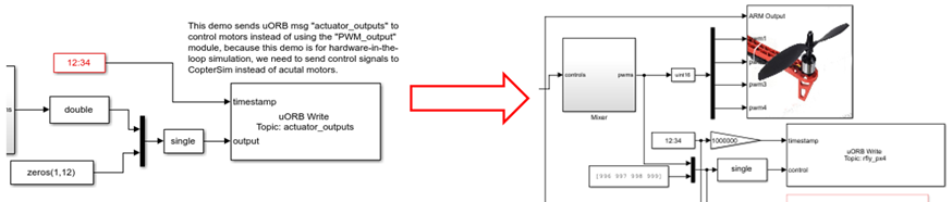
At the same time, the output of the hardware-in-the-loop simulation model is replaced with the motor module from the RflySim platform’s PSP toolbox. Additionally, a uORB message named ‘rfly_px4’ is added. After burning this configuration, the MAVLink protocol can be used to display the aircraft’s flight status on the upper computer program.
After modifying the code through automatic code generation, burn it into the aircraft. Power up the aircraft, connect the local computer to the telemetry, open the upper computer control file in Simulink, set the COM port, and then the experiment can be unlocked. The modified routine file is shown in the diagram below.
Open the upper computer’s Simulink model file to send messages and control the unmanned aircraft. The overall layout is as shown in the diagram below, with control command settings concentrated on the left and top, and the display of return results concentrated on the right.

Next, we will provide a detailed explanation of each section’s functionality. As shown in the diagram below, there are two key control switches on the transmitting end. The one at the top is the ‘Command Transmission Switch,’ and the one below it is the ‘Unlock and Lock’ switch.
When the ‘Command Transmission Switch’ is set to Off, any modifications on Mav_Control_Quadrotor.slx will not take effect, meaning no valid commands will be sent. When the ‘Command Transmission Switch’ is set to On, the ‘Unlock and Lock’ switch becomes effective, and the settings for roll, pitch, yaw, and throttle will also take effect.
The ‘Unlock and Lock’ switch is used to control motor unlocking. During the initial unlocking, it takes three steps to unlock the motors: The first step is to switch the ‘Unlock and Lock’ switch to Arm, wait for 2 seconds, and the motors will emit a beep sound. The second step is to switch the ‘Unlock and Lock’ switch to Disarm, wait for 2 seconds, and the motors will emit another beep sound. The third step is to switch the ‘Unlock and Lock’ switch back to Arm, completing the motor unlocking.
Warning ![]() : Before unlocking the motors, carefully check the settings for throttle, desired roll angle, desired pitch angle, and desired yaw angle. Otherwise, there is a risk of excessive RPM damaging the aircraft or causing injury.
: Before unlocking the motors, carefully check the settings for throttle, desired roll angle, desired pitch angle, and desired yaw angle. Otherwise, there is a risk of excessive RPM damaging the aircraft or causing injury.
Recommendation: For the first experiment, set the throttle value to the minimum, and set the desired roll angle, desired pitch angle, and desired yaw angle to 0. Once familiar with the basic use of the platform, adjust the throttle value, desired roll angle, desired pitch angle, and desired yaw angle as needed.

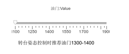
Throttle Setting: As shown in the slider below, you can adjust the throttle value. The throttle value can be understood as the PWM pulse width, typically supported by brushless motors in the range of 1000-2000. However, for safety reasons, it is recommended to set it between 1100-1900. When the slider is at the far left, it will be set to the minimum value of 1100, and when it is at the far right, it will be set to the maximum value of 1900. When performing attitude control on the V200 aircraft on the platform, it is advisable to set the throttle between 1300-1400.
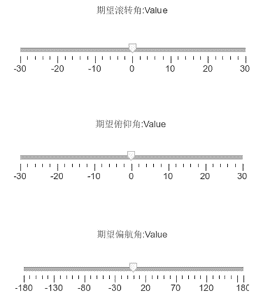
Desired Attitude Settings: As shown below, you can set the desired roll angle, pitch angle, and yaw angle. The desired roll angle and pitch angle can be set between -30° to 30°, and it is recommended to keep the maximum tilt angle below 20° when starting debugging. The yaw angle supports a range of -180° to 180°, and it can be freely set with relatively little impact on system stability.
On the right side of Mav_Control_Quadrotor.slx, real-time numerical values of Euler angles can be displayed, and the Euler angle curves can be viewed through an oscilloscope. In the bottommost oscilloscope, the throttle values can be displayed.

When designing a controller, it is often necessary to verify whether the control logic meets expectations. At such times, it is essential to examine the raw output of the controller. The module shown in the diagram below can display the raw output of the controller, i.e., the pulse width of the PWM wave for each motor. This functionality is only available when connected to the flight controller via USB, as the telemetry connection has a lower data rate, and corresponding messages may not be sent.


The principles mentioned above can be further explored in detail in the 11th chapter of ‘Quan Quan. Introduction to Multicopter Design and Control. Springer, Singapore, 2017’ or ‘Quan Quan. Du Guangxun, Zhao Zhiyao, Dai Xunhua, Ren Jinrui, Deng Heng (trans.). Design and Control of Multicopter Aircraft. Publishing House of Electronics Industry, 2018.’. For more detailed information, please visit https://doc.rflysim.com . The basic and advanced trial versions of RflySim can be obtained by providing your email address through the download link at https://rflysim.com/download . For the full-featured complete version, please inquire at service@rflysim.com .