How to Fly a Quadcopter?

No.1:Getting Started & Drone Controls

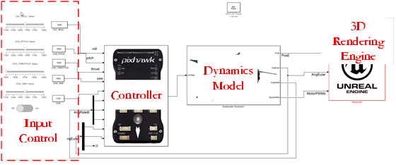
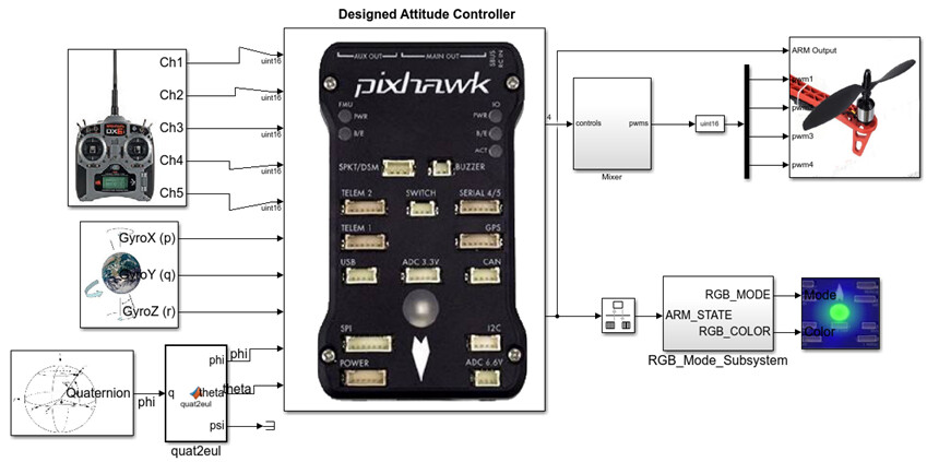
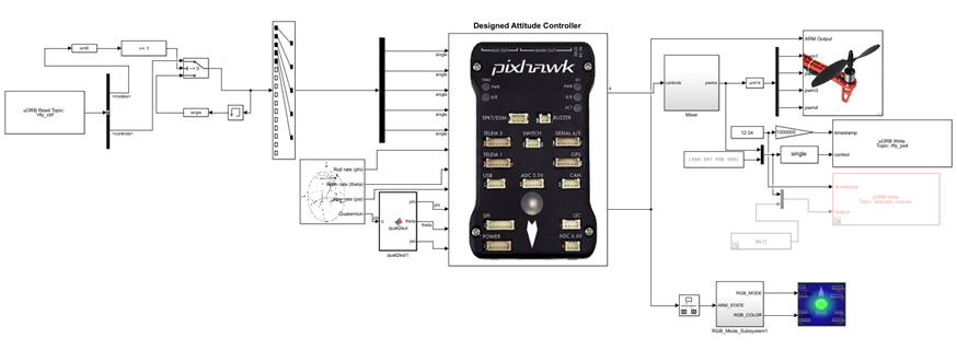
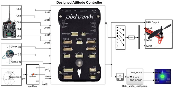
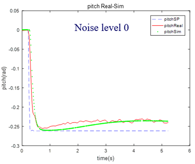
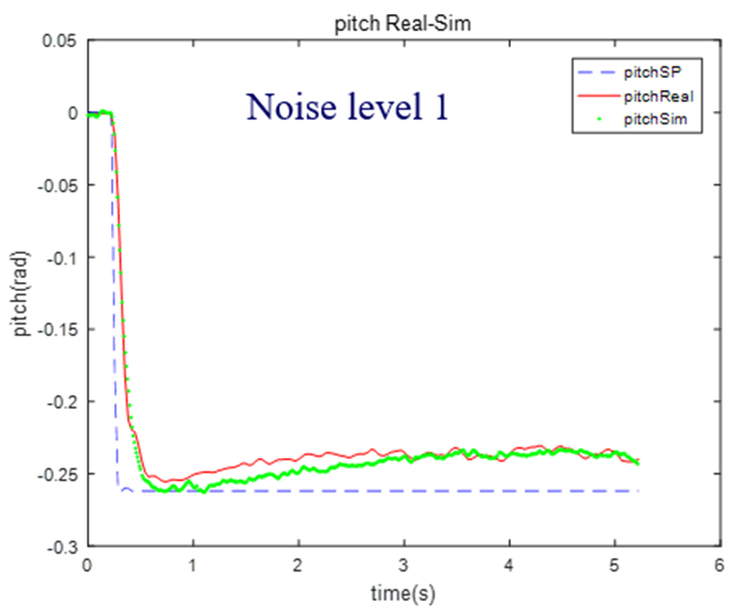
In this series of articles, you will learn how to collaborate in the development of your drone for stable flight using the PX4 and RflySim platforms. All our development is done within a Windows environment, significantly reducing the entry barrier for beginners. I will introduce the control system of a quadcopter drone, explain how to build the drone control system in Simulink, perform digital co-simulation of the control system, simulate software-in-the-loop (SITL) and hardware-in-the-loop (HITL), and complete the entire development process for actual flight.

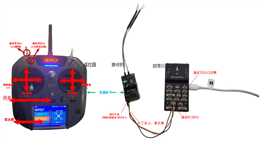
When you’re learning to fly a drone, making it follow your desired trajectory becomes the primary focus. Once you know how to operate a drone for flight, it creates a complete flying experience. When you start for the first time, gently push the control sticks, and the drone will make slight movements. As you become more proficient, you can perform more challenging maneuvers. (Note: For simplicity, this article assumes that the left stick controls yaw and throttle, while the right stick controls roll and pitch. Some remote controllers and receivers allow you to switch control modes according to your comfort).

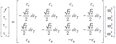
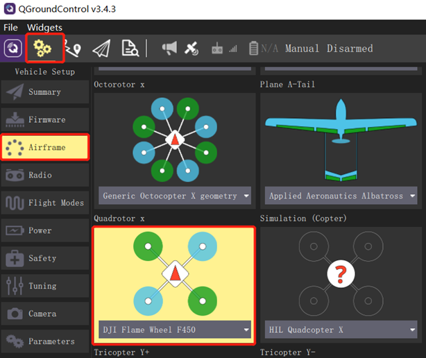
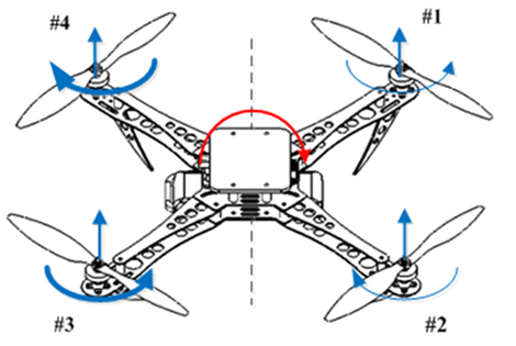
In a quadcopter drone, the four propellers are numbered according to convention, as shown in the figure below, with #1 and #3 rotating counterclockwise, and #2 and #4 rotating clockwise. When we control the drone to fly in different attitudes, the controller adjusts the motor speeds accordingly.

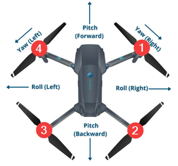
Drones primarily have four attitude control channels:
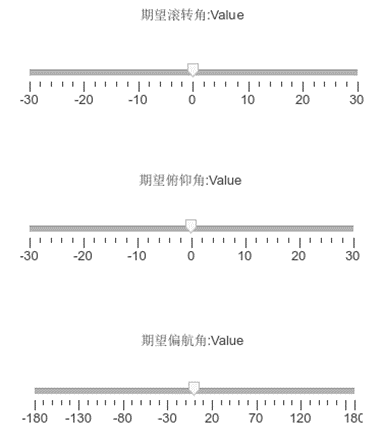
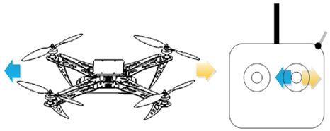
Roll: Achieved by pushing the right stick to the left or right, controlling the drone’s lateral movement. This is accomplished by pushing the right stick on the controller to the left or right. It’s called “roll” because it effectively rolls the drone. For example, when you push the right control stick to the left, the flight control system simultaneously decreases the speed of propellers #3 and #4 while increasing the speed of propellers #1 and #2 by the same amount. This creates an unbalanced torque, causing the aircraft to roll and tilt to the left. Consequently, a lateral force is generated to the left. Simultaneously, the vertical component of lift decreases and is no longer equal to the weight of the multirotor. Therefore, it’s necessary to increase the speed of all four propellers to compensate for gravity, enabling horizontal leftward flight of the multirotor. The corresponding remote control operation for horizontal lateral movement is shown in the diagram.
image
image

Pitch: Achieved by pushing the right stick forward or backward, causing the drone to tilt and move forward or backward. For example, when you push the right control stick upward, the flight controller will simultaneously decrease the speed of propellers #1 and #4 by the same amount while decreasing the speed of propellers #2 and #3 by the same amount. This action results in the quadcopter pitching forward. Consequently, a forward force is generated. Simultaneously, the vertical component of lift decreases and is no longer equal to the weight of the multirotor. Therefore, it’s necessary to increase the speed of all four propellers to compensate for gravity, enabling horizontal forward flight of the multirotor.
image
image
Yaw: Achieved by pushing the left stick to the left or right, causing the drone to rotate to the left or right. Essentially, it makes the drone rotate clockwise or counterclockwise. For example, when you push the left control stick to the right, the drone will rotate clockwise. In this case, the flight controller will simultaneously decrease the speed of propellers #2 and #4 by the same amount while increasing the speed of propellers #1 and #3 by the same amount. This action balances the torque for both forward and backward flight as well as left and right flight. According to Newton’s third law, every action has an equal and opposite reaction. Therefore, since the counterclockwise speed of propellers #1 and #3 has increased, it results in an increased clockwise yaw torque. Conversely, the counterclockwise speed of propellers #2 and #4 has decreased, leading to a decreased counterclockwise yaw torque. Ultimately, this generates a clockwise yaw torque, causing the quadcopter to rotate clockwise.
image
image
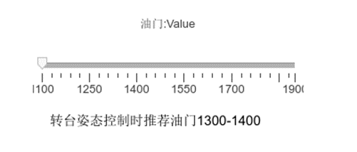
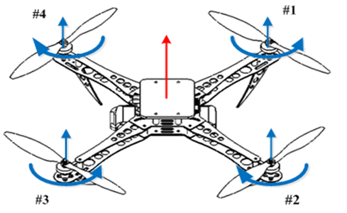
Throttle: To increase the throttle, push the left control stick forward. To decrease it, pull the stick backward. This controls the drone’s altitude. During flight, you should always maintain proper throttle control. To increase the throttle, push the left control stick forward, and to decrease it, pull the stick backward. Ensure that you don’t cut the throttle completely until you’re a few inches above the ground. Otherwise, you might damage the drone, and your training will be cut short. For example, when you push the left control stick forward, the flight controller will simultaneously increase the speed of all four propellers by the same amount, increasing the total lift force generated by the propellers while keeping torque at zero. If the quadcopter is placed on a level surface, when the lift force exceeds gravity, the quadcopter will ascend. Otherwise, if all four propellers’ speeds are decreased by the same amount, the quadcopter will descend. The remote control operations for ascent and descent are shown in the diagram, with red arrows indicating throttle increase, and green arrows indicating throttle decrease.
image
image
Multicopter aircraft, though small like sparrows, are comprehensive in their capabilities. They span across eight primary disciplines, including mechanics, mechanical engineering, electronic science and technology, information and communication engineering, electrical engineering, instrumentation science and technology, control science and engineering, and computer science and technology. The characteristics of multicopter aircraft provide tangible and hands-on practical experience for these respective fields, especially in the realm of control practices.


For more detailed information, please visit https://doc.rflysim.com . The basic and advanced trial versions of RflySim can be obtained by providing your email address through the download link at https://rflysim.com/download . For the full-featured complete version, please inquire at service@rflysim.com .

3 Likes

No.2:Quadcopter Dynamics Model Construction

We have studied the four attitude control channels of the drone: Roll, Pitch, Yaw, and Throttle, along with their operations and effects during flight. When designing the attitude controller for a quadcopter drone, we face complex dynamics and control challenges, requiring a comprehensive consideration of the aircraft’s stability, agility, and precision. The task of the attitude controller is to ensure that the drone maintains the desired attitude during flight, meaning the aircraft’s attitude angles (Pitch, Roll, and Yaw) change in a predetermined manner to accomplish various flight tasks and respond to external disturbances. Before designing the attitude controller, it is essential to have an in-depth understanding of the dynamic model of the quadcopter drone. The dynamics of a quadcopter drone involve multiple variables, including motor speeds, propeller thrust, and the distribution of the aircraft’s mass. Understanding these dynamic relationships is crucial for designing an effective attitude controller. Additionally, considering external factors such as wind, disturbances, and sensor errors that a drone may encounter during actual flight, it is necessary to establish robust and adaptive control algorithms to ensure stable control of the aircraft in various environmental conditions.

In this article, we will explore a quadcopter drone attitude controller design method based on a PID controller. We will introduce the basic principles of the controller, the design steps, and validate the controller’s performance through mathematical models and simulation experiments. Through this design approach, our aim is to achieve precise control and stable flight of the drone in different operational scenarios.

The power system typically includes propellers, motors, electronic speed controllers (ESCs), and batteries. The power system is a critical component of a multirotor, determining key performance factors such as hover time, payload capacity, flight speed, and range. The components of the power system need to be matched and compatible with each other; otherwise, malfunctions may occur, potentially leading to accidents. For example, in certain conditions, aggressive maneuvers by the pilot may cause the current drawn by the ESC to exceed its safety threshold, resulting in motor shutdown, which is highly dangerous during flight. Below, we will introduce the propellers, motors, electronic speed controllers, and batteries separately.

(1) Rigid Body Kinematic Model: Independent of mass and force, focusing on parameters such as position, velocity, attitude, and angular velocity. Often modeled using a point mass.

(2) Rigid Body Dynamic Model: Different from the general rigid body dynamic model, the thrust direction always aligns with the negative direction of the body axis Zb.

(3) Control Efficiency Model: The distinction between hexacopters and quadcopters lies in this control efficiency model.

(4) Power Unit Model: The entire power mechanism consisting of brushless DC motors, ESCs, and propellers. The input is the motor throttle command ranging from 0 to 1, and the output is the propeller speed.


Through mathematical derivation, we can obtain three representation methods for the rigid body model of quadcopter flight control as follows:
Euler Angle-Based Model:
image
Based on the rotation matrix model:
image
Based on the quaternion model:
image
In the control efficiency model, the total thrust acting on the aircraft is:
image
For X-shaped quadcopters, the torque produced by the propellers is:
image
image
The control unit model can be represented as:
image
image
Where motor throttle Q is the input, motor speed W is the output, and Tm is the dynamic response constant of the motor.

The principles mentioned above can be further explored in detail in the 11th chapter of ‘Quan Quan. Introduction to Multicopter Design and Control. Springer, Singapore, 2017’ or ‘Quan Quan. Du Guangxun, Zhao Zhiyao, Dai Xunhua, Ren Jinrui, Deng Heng (trans.). Design and Control of Multicopter Aircraft. Publishing House of Electronics Industry, 2018.’

The complete multirotor model allows engineers and designers to comprehensively design and analyze unmanned aerial vehicle (UAV) systems. This encompasses all aspects from motors, propellers to sensors, and control systems. Through the model, a better understanding of the interactions between different parts of the system can be gained, leading to more informed design decisions. Additionally, the model is a crucial tool for the development, testing, and optimization of flight control algorithms. By implementing different control strategies in the model, engineers can assess their performance in various scenarios, tune parameters, and validate the stability and robustness of the algorithms. Prior to actual flight, simulation verification through the model helps identify potential issues and improve system design. This contributes to enhancing the reliability and safety of the system, reducing unexpected risks during experiments and real flights. Below, we will construct a complete multirotor model using MATLAB/Simulink."

Figure 1: Power Unit Module Design

Figure 2: Control Efficiency Module

Figure 3: Position Dynamics Module and Attitude Dynamics Module

Figure 4: Attitude Kinematics Module

Figure 5: Connection of Rigid Body Control Module, Power Unit Module, and Control Efficiency Module

The above-mentioned model is encapsulated into submodules, and the connection between the rigid body control module, power unit module, and control efficiency module is illustrated in the above figure.
For more detailed information, please visit https://doc.rflysim.com . The basic and advanced trial versions of RflySim can be obtained by providing your email address through the download link at https://rflysim.com/download . For the full-featured complete version, please inquire at service@rflysim.com .

1 Like

No.3: Quadcopter Attitude Control Design

In the preceding two articles, we delved into the fundamental knowledge of quadcopter unmanned aerial vehicles, ranging from their introduction to the construction of the dynamic model, laying a solid theoretical foundation. Now, we step into a new domain, delving into the design of the quadcopter’s attitude controller. Attitude control is a crucial aspect of drone flight, directly influencing the aircraft’s stability and maneuverability.

In this article, we will explore different types of attitude controllers, their design principles, and how to apply them to quadcopter systems. Understanding the attitude control of a quadcopter is a key step in gaining a deep understanding of the principles of drone flight and translating theoretical knowledge into practical flying capabilities.
Before designing a control system, we need to clarify the system’s inputs and outputs. For a quadcopter unmanned aerial vehicle, input data can be divided into:

  1. Signals from remote control channels Ch1~Ch5, with a data range of approximately 1100-1900. Calibration or consideration of dead zones is needed when handling remote control data.
  2. Angular rate feedback AngRateB, represented by three components p, q, r (units: rad/s), representing roll rate (rotation along the body x-axis), pitch rate (rotation along the body y-axis), and yaw rate (rotation along the body z-axis).
  3. Quadcopter Euler angles (units: rad). Here, we mainly consider roll and pitch angles, without considering yaw control.

Output data:

  1. PWM control signals for four motors, with a data range of 1000-2000.
  2. Unlock identifier, data type: boolean.

Implementation effect: CH3 throttle channel controls the ascent and descent of the aircraft; pushing the pitch joystick forward (i.e., CH2<1500) controls the quadcopter to fly forward; pushing the roll joystick to the left (i.e., CH1<1500) controls the quadcopter to fly left; pulling down the toggle switch (i.e., CH5>1500) unlocks the controller. Here, we provide a well-designed example, which can be found in the file “\PX4PSP\RflySimAPIs\0.ApiExps\3.DesignExps\Exp1_AttitudeController.slx” after installing the RflySim platform. Open this file, and the Simulink diagram can be seen on the right side. Please carefully read the implementation methods of the sub-modules and improve the functionality. You can also incorporate control of the yaw channel.
image
image
Generating Controller Submodule: Select all controllers in the above text using the mouse (or press CTRL+A on the keyboard), right-click, and choose ‘Create Subsystem For Selection’ to encapsulate the controllers into a submodule. Right-click on this submodule, select ‘Mask’ - ‘Create Mask,’ and in the ‘Icon drawing commands’ input box (see the upper-right figure), enter “image(‘./icon/Pixhawk.png’);”. Click ‘OK,’ and adjust the interface positions to obtain the submodule as shown in the lower-right.


Integration of Controller, Model, and RflySim Display Module: Building upon the controller design discussed earlier, we need to set up the controller’s inputs and outputs. The inputs include the simulated remote control channels CH1~CH5 and feedback signals, while the outputs are PWM signals. PWM serves as the input for the model, and the model outputs the aircraft’s state variables, which act as feedback for the controller and input for the RflySim 3D display module. We need to reestablish the connections between the controller and the quadcopter model.
Since the remote control signals are not available at this point, you can use constant values as substitutes or use functions to simulate corresponding remote control actions. Here, we provide an example where the controller and virtual remote control signals are already connected.

image

Double-click on the ‘Rflysim3D’ software in the RflySim platform to open it, then click the ‘Start Simulation’ button on the Simulink toolbar (see the upper-right figure) to begin the simulation. At this point, you can observe in Rflysim3D (see the figure on the right) that after a period of ascent, you can use the sliders in Simulink to simulate basic control operations of the quadcopter as if controlled by a remote controller.

The principles mentioned above can be further explored in detail in the 11th chapter of ‘Quan Quan. Introduction to Multicopter Design and Control. Springer, Singapore, 2017’ or ‘Quan Quan. Du Guangxun, Zhao Zhiyao, Dai Xunhua, Ren Jinrui, Deng Heng (trans.). Design and Control of Multicopter Aircraft. Publishing House of Electronics Industry, 2018.’. For more detailed information, please visit https://doc.rflysim.com . The basic and advanced trial versions of RflySim can be obtained by providing your email address through the download link at https://rflysim.com/download . For the full-featured complete version, please inquire at service@rflysim.com .

No.4:Hardware-in-the-Loop Simulation (HITL) based on RflySim

In the previous article, we achieved a software-in-the-loop simulation of a quadcopter based on RflySim and MATLAB/Simulink. We conducted preliminary validation of the control and dynamics models we constructed. In order to meet the standards for actual flight, additional experiments such as hardware-in-the-loop simulation and platform flight are required. In this section, we will delve into hardware-in-the-loop simulation based on the RflySim platform.

Introduction to MATLAB/Simulink Automatic Code Generation: Automatic code generation technology frees system engineers from the burdensome task of coding, allowing upper-level software designers to focus on their functional design without the need for in-depth knowledge of underlying hardware and driver programs. Since 2010, repetitive C code writing in the automotive industry has rapidly been replaced by automatic code generation technology. According to a conservative estimate by Infineon, by 2020, 90% of 32-bit microcontroller code was generated automatically.

The development of automatic code generation technology is based on the MATLAB/Simulink tool, utilizing the Real-Time Workshop (RTW) tool introduced by MathWorks to compile code for developed models. Subsequently, the code is downloaded to the target controller by invoking the target application program. This approach not only reduces the number of developers but also significantly accelerates the development process.

After model construction is completed, Simulink allows users to choose the model’s operating mode and code generation options. Different target codes can be automatically generated by configuring solver step size and target hardware options. However, directly generated generic embedded C code has poor readability and cannot configure corresponding hardware drivers. If one were to manually link relevant driver programs for the target hardware, the workload would be enormous, leading to a loss of the advantages of automatic code generation. The image below illustrates generic C code configuration options and the corresponding generated code, which has poor readability and is not convenient for target hardware configuration.

Through the study of Simulink-related code control files, the applied automatic code generation mechanism can directly generate all target hardware code with a single click and call relevant compilers to automatically generate project files. This eliminates the work stages associated with linking model application layer code and low-level driver associations. The Target Language Compiler (TLC) language in Simulink serves as a bridge between the model and target code and is an interpretive language. The role of TLC files is to convert the rtw files generated by Simulink into specialized code for the target hardware, controlling the code generation process. Customization of key TLC files enables the customization of the main function, module parameter passing, system header file inclusion, calling target compilers, and more, achieving automatic code generation. Through the development of individual functional components, a complete Target Support Package (TCP) is ultimately formed. The RflySim platform adopts Pixhawk series target hardware, enabling the automated deployment of code on flight control hardware supported by PX4 software. The diagram below illustrates the framework of software-in-the-loop simulation.
image
The RflySim platform provides a complete template file for automatic code generation, which can be found after the software is fully installed at: “*\PX4PSP\RflySimAPIs\5.RflySimFlyCtrl\0.ApiExps\3.DesignExps\Exp3_BlankTemp.slx”. To perform software-in-the-loop simulation, the controller module constructed during simulation setup is independently copied and pasted into this template file. Subsequently, relevant input and output interfaces are extracted from the Simulink PSP toolbox, and connections are made with the controllers from step six. The result after connecting the lines is shown in the diagram below.


Here, it’s important to note that, since hardware-in-the-loop simulation will be conducted instead of actual flight, the PWM output interface needs to send the actuator_outputs message to Pixhawk via uORB messaging. This is achieved directly using the PWM output module from the PSP toolbox.

In the example above, raw data from the remote controller is directly read. However, in the example “Exp4_AttitudeSystemCodeGen.slx” shown in the bottom-right diagram, the uORB message “manual_control_setpoint” is used to obtain calibrated and normalized remote controller data (pitch, roll, yaw: -11, throttle: 01) instead of directly reading the remote controller PWM signals. This approach is more convenient, reliable, and compatible with any remote controller without calibration concerns.

By clicking the “Compile” button on the Simulink toolbar, the code is automatically compiled, generating the autopilot firmware. The successful compilation is indicated by the result shown in the top-right. Connect the computer and Pixhawk autopilot using a USB cable, and then use the “Upload Code” feature to download the firmware to Pixhawk. The successful download is indicated by the result shown in the bottom-right.


Connect the receiver to Pixhawk 6C using three-color DuPont wires as shown in the diagram on the right. Then, connect Pixhawk 6C to the computer using a USB data cable. At this point, you should see the blue light on Pixhawk 6C illuminate, and the light on the receiver remains a steady red. Turn on the remote controller (with the throttle stick pulled to the lowest position), and observe that the light on the receiver changes to a steady blue.

Open the QGC ground station and connect to the Pixhawk 6C autopilot.
1)Navigate to the “Airframe” tab and ensure that the model is in “HIL Quadcopter X” frame mode.
2)Go to the “Flight Modes” tab and verify that the “Arm Switch Channel” toggle switch is set to CH5.
3)Close the QGC ground station.

The flight controller is connected to the computer via a USB cable. Double-click the HITLRun shortcut on the desktop, enter the COM port of the flight controller in the pop-up dialog box, and the computer will automatically open RlySim3D, QGroundControl, and CopterSim software, enabling one-click startup for hardware-in-the-loop simulation.
image

Wait for CopterSim to display “PX4: GPS 3D fixed & EKF initialization finished.” Once this message appears, you can use the CH5 toggle switch on the remote controller to unlock the multirotor. You can then manipulate the remote controller to make the multirotor perform corresponding actions. As shown in the diagram on the right, RflySim3D will display the current flight status of the multirotor.


The principles mentioned above can be further explored in detail in the 11th chapter of ‘Quan Quan. Introduction to Multicopter Design and Control. Springer, Singapore, 2017’ or ‘Quan Quan. Du Guangxun, Zhao Zhiyao, Dai Xunhua, Ren Jinrui, Deng Heng (trans.). Design and Control of Multicopter Aircraft. Publishing House of Electronics Industry, 2018.’. For more detailed information, please visit https://doc.rflysim.com . The basic and advanced trial versions of RflySim can be obtained by providing your email address through the download link at https://rflysim.com/download . For the full-featured complete version, please inquire at service@rflysim.com .

No.5:Quadcopter Test Flight Experiment Based on RflySim

This experiment involves the construction of a quadcopter flight controller in MATLAB/Simulink. Control commands are transmitted through Simulink to control the attitude of the quadcopter on the platform. Proficiency in MAVLink communication and the tuning of parameters for quadcopter attitude control is essential.

The key content is divided into two parts: MAVLink communication and controller design. In this experiment, the MAVLink protocol is used for communication between the flight controller and the upper computer. On one hand, control commands sent by MATLAB are transmitted to the flight controller through the MAVLink protocol. On the other hand, the flight controller sends key status information to MATLAB for display through the MAVLink protocol, facilitating debugging and analysis. The controller adopts the classical PID controller, and to ensure the safety of the controller, it is necessary to limit the calculation results of each channel.

MAVLink (Micro Air Vehicle Link) is a communication protocol for small unmanned vehicles, first released in 2009. This protocol is widely used for communication between Ground Control Stations (GCS) and unmanned vehicles, as well as for internal communication between onboard computers and Pixhawk on vehicles. The protocol defines the rules for parameter transmission in the form of a message library. MAVLink protocol supports various vehicles such as unmanned fixed-wing aircraft, unmanned rotorcraft, unmanned vehicles, and more.

The controller adopts the widely used PID controller. The PID control algorithm consists of Proportional (P), Integral (I), and Derivative (D) components. PID control involves using the sum of the proportional, integral, and derivative of the variable deviation as the control input, calculating the output value as a control method. The structure diagram of a traditional PID control system is shown in the figure.

The proportional ‘P’ parameter in the figure plays a role in correcting deviations. A larger P parameter increases sensitivity to errors, resulting in faster error correction and quicker system response. However, an excessively large P parameter can lead to significant overshooting. The integral ‘I’ parameter contributes to improving accuracy; a larger I value leads to smaller tracking errors, resulting in more precise system tracking. The derivative ‘D’ parameter helps suppress overshooting by reflecting the rate of change of the error signal. It can decelerate the system when tracking is close to the desired target, and generally, the D parameter is not set too high, as an excessively large D parameter can cause system oscillations.
The PID control algorithm is widely used due to its simple structure, good stability, high reliability, and convenient tuning, making it a major technology in industrial control. Its main advantage lies in not requiring system modeling or identification. Once designed, it can be fine-tuned through experimentation. For general unmanned systems, which can be complex to model, the PID control algorithm is frequently employed.

The overall framework of this experiment is illustrated in the diagram above. The MATLAB controller is designed using the PSP toolbox on the upper computer. The MATLAB controller can be compiled directly into a Simulink APP that can be used on the flight controller. By burning the Simulink APP into the flight controller, the controller can compute control laws and manipulate the unmanned aircraft on the platform. On the upper computer, the Simulink environment can be used to read the state of the flight controller or send control commands to it. The physical connection between the upper computer and the flight controller can be established via telemetry or USB. While telemetry connection has a slower communication rate, rendering some messages unavailable, a USB connection offers a higher communication speed, enabling the display of all information.
After performing hardware-in-the-loop simulation on the designed model, testing on the platform is necessary before actual flight. The input to the hardware-in-the-loop simulation model is replaced with the uORB message named ‘rfly_ctrl,’ a custom message in the RflySim platform. After burning this configuration, MAVLink protocol is utilized for communication between the flight controller and the upper computer.

At the same time, the output of the hardware-in-the-loop simulation model is replaced with the motor module from the RflySim platform’s PSP toolbox. Additionally, a uORB message named ‘rfly_px4’ is added. After burning this configuration, the MAVLink protocol can be used to display the aircraft’s flight status on the upper computer program.

After modifying the code through automatic code generation, burn it into the aircraft. Power up the aircraft, connect the local computer to the telemetry, open the upper computer control file in Simulink, set the COM port, and then the experiment can be unlocked. The modified routine file is shown in the diagram below.

Open the upper computer’s Simulink model file to send messages and control the unmanned aircraft. The overall layout is as shown in the diagram below, with control command settings concentrated on the left and top, and the display of return results concentrated on the right.

image

Next, we will provide a detailed explanation of each section’s functionality. As shown in the diagram below, there are two key control switches on the transmitting end. The one at the top is the ‘Command Transmission Switch,’ and the one below it is the ‘Unlock and Lock’ switch.

When the ‘Command Transmission Switch’ is set to Off, any modifications on Mav_Control_Quadrotor.slx will not take effect, meaning no valid commands will be sent. When the ‘Command Transmission Switch’ is set to On, the ‘Unlock and Lock’ switch becomes effective, and the settings for roll, pitch, yaw, and throttle will also take effect.

The ‘Unlock and Lock’ switch is used to control motor unlocking. During the initial unlocking, it takes three steps to unlock the motors: The first step is to switch the ‘Unlock and Lock’ switch to Arm, wait for 2 seconds, and the motors will emit a beep sound. The second step is to switch the ‘Unlock and Lock’ switch to Disarm, wait for 2 seconds, and the motors will emit another beep sound. The third step is to switch the ‘Unlock and Lock’ switch back to Arm, completing the motor unlocking.

Warning :warning:: Before unlocking the motors, carefully check the settings for throttle, desired roll angle, desired pitch angle, and desired yaw angle. Otherwise, there is a risk of excessive RPM damaging the aircraft or causing injury.

Recommendation: For the first experiment, set the throttle value to the minimum, and set the desired roll angle, desired pitch angle, and desired yaw angle to 0. Once familiar with the basic use of the platform, adjust the throttle value, desired roll angle, desired pitch angle, and desired yaw angle as needed.

image

Throttle Setting: As shown in the slider below, you can adjust the throttle value. The throttle value can be understood as the PWM pulse width, typically supported by brushless motors in the range of 1000-2000. However, for safety reasons, it is recommended to set it between 1100-1900. When the slider is at the far left, it will be set to the minimum value of 1100, and when it is at the far right, it will be set to the maximum value of 1900. When performing attitude control on the V200 aircraft on the platform, it is advisable to set the throttle between 1300-1400.

image

Desired Attitude Settings: As shown below, you can set the desired roll angle, pitch angle, and yaw angle. The desired roll angle and pitch angle can be set between -30° to 30°, and it is recommended to keep the maximum tilt angle below 20° when starting debugging. The yaw angle supports a range of -180° to 180°, and it can be freely set with relatively little impact on system stability.

image

On the right side of Mav_Control_Quadrotor.slx, real-time numerical values of Euler angles can be displayed, and the Euler angle curves can be viewed through an oscilloscope. In the bottommost oscilloscope, the throttle values can be displayed.

When designing a controller, it is often necessary to verify whether the control logic meets expectations. At such times, it is essential to examine the raw output of the controller. The module shown in the diagram below can display the raw output of the controller, i.e., the pulse width of the PWM wave for each motor. This functionality is only available when connected to the flight controller via USB, as the telemetry connection has a lower data rate, and corresponding messages may not be sent.

image

图片1

The principles mentioned above can be further explored in detail in the 11th chapter of ‘Quan Quan. Introduction to Multicopter Design and Control. Springer, Singapore, 2017’ or ‘Quan Quan. Du Guangxun, Zhao Zhiyao, Dai Xunhua, Ren Jinrui, Deng Heng (trans.). Design and Control of Multicopter Aircraft. Publishing House of Electronics Industry, 2018.’. For more detailed information, please visit https://doc.rflysim.com . The basic and advanced trial versions of RflySim can be obtained by providing your email address through the download link at https://rflysim.com/download . For the full-featured complete version, please inquire at service@rflysim.com .

1 Like

No.6:Outdoor Real Flight Experiments of Quadcopters Based on RflySim

Aircraft Assembly: The actual flying aircraft we use is the FeiSi Laboratory X450 aircraft, as shown in the diagram below. Various calibrations and parameter adjustments have been carried out before the aircraft leaves the factory. During actual flight, it is necessary to modify the frame type of Pixhawk 6C from “HIL Quadcopter X” to “DJI Flame Wheel F450” in QGC (Ground Control Software), import the official aircraft parameter file, check the status of various aircraft sensors, and proceed with the test flight once everything is confirmed to be correct.

Considering the uncertainties in actual flight and the lack of complete failure protection logic in the self-generated control algorithm, safety issues should be thoroughly considered during real flight. Actual flight experiments should be conducted in relatively open areas, such as grasslands, while ensuring good weather conditions and low wind speeds. Under these conditions, first flash the firmware and parameters corresponding to the official FeiSi X450 aircraft version, conduct a test flight to confirm that the aircraft can take off normally. Afterward, flash the firmware generated by the controller model designed for this experiment, and use a remote controller to control the multi-rotor to verify the actual performance of the controller.
Adjusting the Simulink Controller: Open the Simulink file, as shown in the figure, change the output of uORB to the PWM_out output module provided by the PSP toolbox, regenerate the code, and download it to Pixhawk 6C. An example is provided in the file “0.ApiExps\3.DesignExps\Exp5_AttitudeSystemCodeGenRealFlight_old.slx” (or use the slx routine without the ‘old’ suffix). Note that in this example, unlocking via the throttle stick on the remote controller is not required during real flight, but toggling the CH5 switch is necessary for unlocking (sometimes it may need to be toggled twice).

Going through a pre-flight checklist will keep you and your drone safe. Here’s a checklist you can use before each flight:

WEATHER & SITE SAFETY CHECK

  • Chance of precipitation less than 10%

  • Wind speed under 15 knots (less than 20 mph)

  • Cloud base at least 500 feet

  • Visibility at least 3 statute miles (SM)

  • If flying at dawn / dusk, double-check civil twilight hours

  • Establish take-off, landing, and emergency hover zones

  • Potential for electromagnetic interference?

  • Look for towers, wires, buildings, trees, or other obstructions

  • Look for pedestrians and/or animals and set up safety perimeter if needed

  • Discuss flight mission with other crew members if present
    VISUAL AIRCRAFT / SYSTEM INSPECTION

  • Registration number is displayed properly and is legible

  • Look for abnormalities—aircraft frame, propellers, motors, undercarriage

  • Look for abnormalities—gimbal, camera, transmitter, payloads, etc.

  • Gimbal clamp and lens caps are removed

  • Clean lens with microfiber cloth

  • Attach propellers, battery/fuel source, and insert SD card / lens filters
    POWERING UP

  • Turn on the remote control and open up DJI Go 4 app

  • Turn on aircraft

  • Verify established connection between transmitter and aircraft

  • Position antennas on transmitter toward the sky

  • Verify display panel / FPV screen is functioning properly

  • Calibrate Inertial Measurement Unit (IMU) as needed

  • Calibrate compass before every flight

  • Verify battery / fuel levels on both transmitter and aircraft

  • Verify that the UAS has acquired GPS location from at least six satellites

TAKING OFF

  • Take-off to eye-level altitude for about 10-15 seconds
  • Look for any imbalances or irregularities
  • Listen for abnormal sounds
  • Pitch, roll, and yaw to test control response and sensitivity
  • Check for electromagnetic interference or other software warnings
  • Do one final check to secure safety of flight operations area
  • Proceed with flight mission

GETTING YOUR DRONE OFF THE GROUND

Before we get started, let’s cover a few important safety protocols and recommendations. it is important to note that drones are not toys and can be dangerous. Let’s lay out some initial safety precautions to ensure a safe flight:

  • If you’re about to crash into something, turn the throttle down to zero, so you don’t potentially destroy your drone, injure somebody, or injure yourself.

  • Take out the battery of the drone before doing any work on it. If it turns on accidentally and the propellers start spinning, you might have a tough time doing future flights with missing fingers.

  • Keep your fingers away from the propellers when they’re moving.

  • If you’re a beginner learning to fly indoors, tie the drone down or surround it with a cage.

Choosing a safe and legal flight location is also crucial for a safe operation. Here are some tips on finding the perfect spot:

  • We suggest starting out in a large, open space, such as a park or a field. Many people prefer to learn on grassy ground, so if the drone needs to make a crash landing, it will at least have some sort of cushion.

  • Stay away from people or animals.

  • Avoid windy conditions as a beginner and be aware of your drone’s performance limitations (refer to user manual).

  • Lastly, choose a legal, safe, and visually interesting location to fly your drone. After a round of comprehensive research, our team compiled a list of where to fly a drone in various cities across the country.

Alright! Now that you understand the controls and you’ve taken all of the right safety precautions, you’re ready to fly.

  • To get your drone in the air, the only control you need is the throttle.

  • Push the throttle (left stick) up very slowly, just to get the propellers going. Then stop.

  • Repeat this multiple times and until you’re comfortable with the throttle’s sensitivity.

  • Slowly push the throttle further than before, until the copter lifts off the ground. Then pull the throttle back down to zero and let the drone land.

  • If you want to get good visualization, check out this great video from My First Drone。

Read the log data from actual flight and semi-physical simulation. In the top right, with the noise level set to 1, it can be observed that the step response in both the dynamic process and noise level of the semi-physical simulation is relatively close to the step response in actual flight. In the bottom right, with the noise level set to 0, the angles calculated in the semi-physical simulation show no noise, and the dynamic process is close to the actual flight. Note that due to the fact that the frame type “HIL Quadcopter X” in the simulation mode is not exactly the same as the “DJI Flame Wheel F450” used in actual flight, and there are differences in controller parameters, it is normal for there to be some error in the response curves. Additionally, the aerodynamics of the multi-rotor in actual flight are very complex, while the model uses a simplified aerodynamic model, so some error in the final steady-state angle response curve is acceptable.

The principles mentioned above can be further explored in detail in the 11th chapter of ‘Quan Quan. Introduction to Multicopter Design and Control. Springer, Singapore, 2017’ or ‘Quan Quan. Du Guangxun, Zhao Zhiyao, Dai Xunhua, Ren Jinrui, Deng Heng (trans.). Design and Control of Multicopter Aircraft. Publishing House of Electronics Industry, 2018.’. For more detailed information, please visit https://doc.rflysim.com . The basic and advanced trial versions of RflySim can be obtained by providing your email address through the download link at https://rflysim.com/download . For the full-featured complete version, please inquire at service@rflysim.com .