I have some STM32f427VIT6 rev.3 chips on the way and I’m going replace them on my Pixhawks.
I’m confident that I can remove the old chip and solder a new one.
Is anyone still interested in fixing the 1MB limit?
Can anyone help me with the boot-loader as these are stock STM32 chips?
I have a Nucleo board with the ST-LINK/V2-1 debugger/programmer so I think I can load the chip with a firmware/boot-loader this way but I don’t have any experience with ST micro-controllers.
Is it possible do get a .hex or .bin file of the boot-loader and flash it with the ST-LINK/V2-1?
If it all works with a new chip and a boot-loader on it I will make the replacement procedure public for anyone.
I can also do it for anyone who is scared of soldering iron for a small fee.
The 1MB limit is related to the old silicon revision. This is no longer a problem with the rev. 3 silicon (hence why you want to replace your STM32F427 MCUs).
Once you have cloned the repo, run make px4fmuv2_bl in the directory (just running make will make all of the bootloaders - probably not what you need immediately). This should update the one submodule (libopencm3), and compile your bootloader. It will produce a px4fmuv2_bl.bin file in the bootloader directory. You can flash this binary onto the new MCU to address 0x08000000 using your ST-Link.
Additional notes for replacing the MCU:
If you have access to hot air, I would recommend that you use that to remove the chip. If you only have a soldering iron, be careful not to pull up any of the pads under the pins when you desolder them. If using hot air, use a low flow rate so as not to blow the surrounding components (mostly small capacitors) off of their pads.
Needle-nose tweezers are also very useful for initially removing and positioning the new MCU.
Once you have removed the chip, clean the pads using some solder wick, so that everything is clean and there are no shorts
If you have access to a microscope, use it. It will make soldering the chip much much much easier
If you have chip flux, use that when soldering. It will make your life easier, and will make it less likely that you create solder-bridges between the pins
Once you have soldered on the new chip, check adjacent pins for solder bridges - preferably using a multimeter with fine-tipped probes - sometimes the solder bridges can be difficult to see unless you are using a microscope.
Also make sure to check that you don’t have a short between 3V3 and GND.
Once the bootloader is flashed onto the MCU, it should appear on your PC when you connect it via USB. If you are on Linux, you can just run dmesg to see if it has shown up.
Dear @ksschwabe, @gregswf,
I need your help.
My pixhawk damage the mini usb port, and I diy the cable for external usb, but can connect to usb. may be the IC protect usb(NUF2042XV6) damage.
Could you please help me Upload bootloader and firmware via ST-link (v2) without usb. I mean that, welding direct to STM32F4 chip and flash.
Thanks so muchs
Reed Noel
Dear sir,
When I plug usb cable in mini usb cable, some time it have error " usb malfuntiom", and when I keep usb by hand it can connect, so i put by hand so strong, the mini usb broken.
I try welding the new mini usb, so it don’t work. And i weld serval time, it same.
I trying cut the usb cable and weld the 4 pín, ít correct with schematíc of hardware so can’t connect.
Currently, in my pixhawk alteady px4io firmware 1.6.1 and working with qgc. So I wan’t upload new fimware arducopter.px4.
I build firmware succecfully, so don’t know how to upload firmware into pixhawk. I search on the web and .how to upload bootloader via st-link, but not found manual.upload firmware.
Thanks for replies.
Reed Noel
Do you have the firmware binary file already? Not the .px4 firmware file, but the actual binary file that is also produced when you compile the firmware?
When you have the firmware binary file, you can flash it/upload it to the address 0x08004000 with the ST-Link.
Do you want to flash a new bootloader onto your Pixhawk as well? That should be uploaded to the address 0x08000000.
Hi @ksschwabe,
I using windows 10, I have only firmare px4 file, I don’t know how to make bin, hex file firmware. I find on internet but not found.
I make firmware with px4 eclipse application, so don’t know output the bin, hex file.
The .px4 file is a JSON file. You can open it in a text editor and have a look at its contents. It contains a compressed version of the firmware binary as well as additional information that is used by QGroundControl, so that it knows for which Pixhawk board the firmware was compiled for.
You can try and extract the binary file by writing a script to read in the .px4 file, uncompressing the firmware image and then writing it as a binary file. You can then flash that binary file using the ST-Link.
Have a look at the script Firmware/Tools/px_mkfw.py to see how the .px4 file is created in the first place. That will give you a starting point.
Otherwise you can try and upload the firmware via the UART port. If you have a recent bootloader flashed on to your Pixhawk you will be able to upload the firmware on the USART port.
How old is your Pixhawk? And what version of the Pixhawk do you have?
I see in the board of pixhawk , it writting :" Pixhawk 2.4.9".
I trying flash fw via Uart ( telem1, lelem2, uart 4/5), but can’t
Let I trying study py application, I never using it before.
Rgs
Reed Noel,
I have no experience compiling the ArduCopter firmware, so I have no idea where it produces its binaries. Have a look in the directory where the .px4 file is generated and see if there are any .elf, or .bin files there.
I have had a look at the bootloader code for the Px4FMUv2. If you have a “newish” bootloader on your Pixhawk, then you should be able to upload the firmware on UART2 - I don’t know which connector port (telem1, telem2) that is on the Pixhawk board.
Does your board stay in the bootloader? Does the bootloader activity LED flash to show that it is in the bootloader?
If you can use UART port in the bootloader, your can pull the RX line of the UART port to GND when powering on the Pixhawn and it will stay in the bootloader (the bootloader LED will flash).
Hi @ksschwabe,
I saw the folder on the Arducopter with name Binaries, and inside have px4io-v2.elf - [arm/le], what is this file? bootloader or firmware?
Rgs
Reed Noel
As I said, I am not familiar with compiling the ArduCopter firmware, so I can’t be sure.
From the name of the file, it looks like it is the .elf firmware file for the Px4IO chip on the Pixhawk. The Px4IO firmware is compiled into the main Px4 firmware and on startup it usually checks whether the firmware on the Px4IO chip is up to date and then updates it if necessary.
Unfortunately, that is not the firmware file that you need…
Can you flash a new bootloader with st-link and then flash the firmware using mission planner and uart2? You will need an ftdi (uart ttl to usb) adapteradapter to connect the uart to the pc.
You can try with qgroundcontrol too.
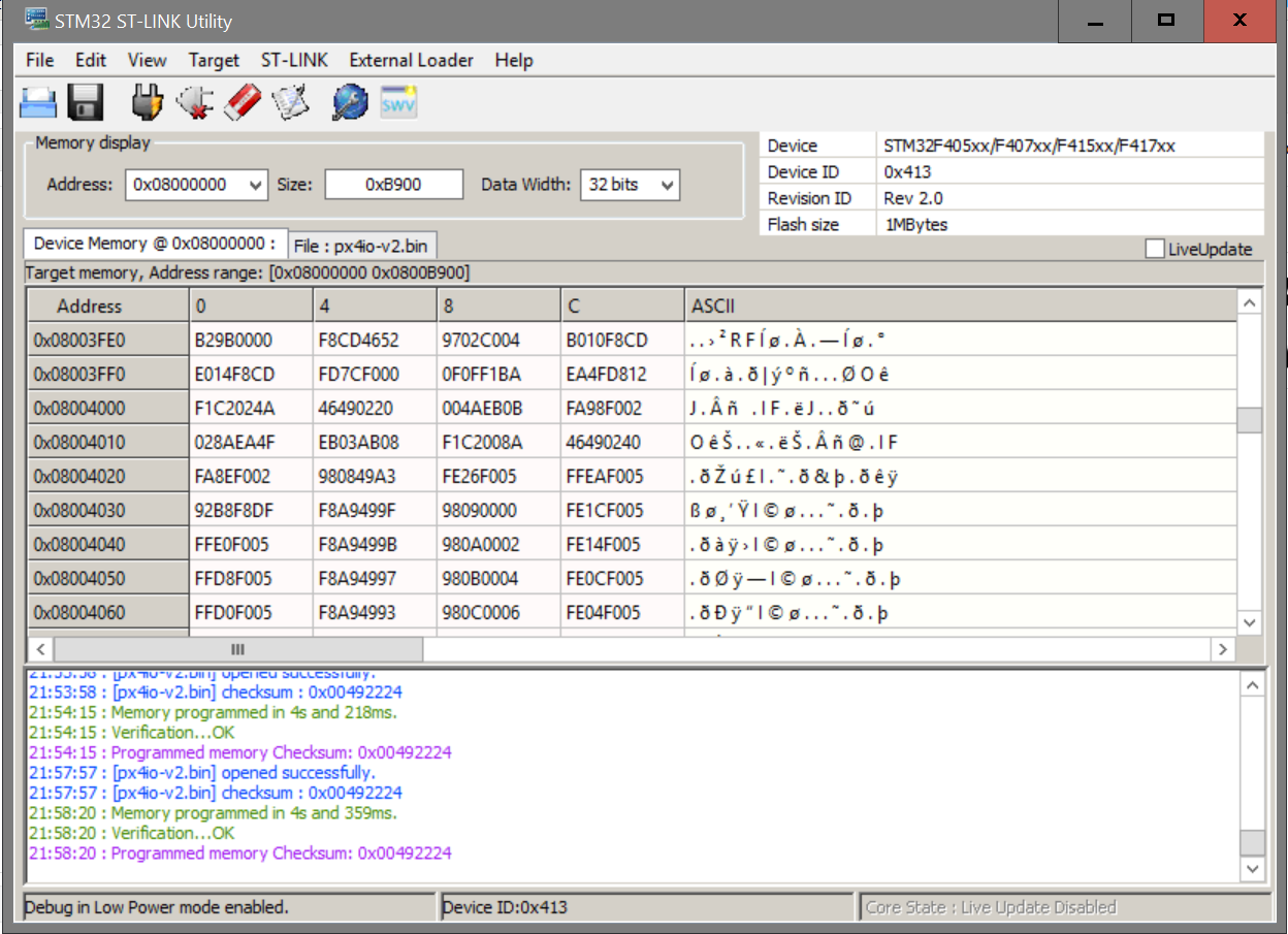
If I upload Firmware without eraset sector, it error data in 0x08004000.
I think that, If I select erase, the bootloader will be wrong, is this right ?
@ReedNoel: Yes you have to erase the sector before trying to flash the bootloader onto the microcontroller, otherwise the write will not be successful.
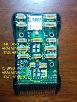
I am a bit confused by what you are trying to flash onto which microcontroller. The picture that you posted shows that the device is an STM32F4xxx microcontroller, which would be the main microcontroller for the Pixhawk. But it looks as if you are uploading the Px4IO-v2 firmware. This is the firmware meant for the STM32F1 IO microcontroller.
Are you trying to flash the latest bootloader onto the main microcontroller? Or just the main firmware? The bootloader must be flashed to address 0x08000000 and the main firmware must be flashed to address 0x08004000.