Control allocation roll/pitch torque effectiveness actual meaning

About

While configuring control allocation for a paramotor system (as extension project to the original PX4 Paramotor Project #1 - First flight with PX4), I was a bit puzzled as to what “roll/pitch torque values” for actuators tab actually stands for.

In the documentation, it is noted that it amounts to the ‘effectiveness’ of each actuator to the torque value, and I wanted to resolve som questions on what those values actually mean, by involving a flying wing configuration example.

Flying Wing Example

For flying wing with 2 elevons, the following effectiveness values are set by default:

image

Now, what happens when:

  1. We change Roll torque for Left Elevon to -1.0 (from -0.5), and leave Right Elevon as is? Does the Left Elevon now move “less” than the right elevon for a roll command, as it is more effective now?
  2. We change BOTH Left and Right Elevon’s Roll torque to -/+ 1.0? Does this lead to both elevons moving “less”, as it’s more effective, or does this not matter, as it all gets normalized?

In general, I am wondering exactly what those effectiveness values are supposed to mean. Does the absolute value matter? (e.g. 0.5, or 1.0), or is ‘relative value’ more relevant? (e.g. 0.5 vs 0.5 = 1.0 vs 1.0)

Would love to have some clarification on this! Thank you!

@sfuhrer @bkueng I think both of you probably know the answer to this I suspect :pray:

When you analyze the torques which your control surfaces generate on the CoG of your aircraft based on their deflection, you effectively applied Newtons 2nd Law:

t = f(e)

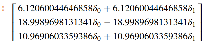
From this equation you see how each deflection, e generates torques, t in the various directions of your aircraft.

However, in controller design, you controllers outputs a torque t , and not a deflection, e, and thus the above equation needs some rework.

We need to find a way, that if we want to generate a specific amount of torque t , what is the deflection angles e needed to generate that torque. To achieve this we need to invert the above equation.

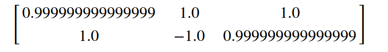
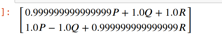
f is known as your control effectiveness equation. Usually this in a nonlinear equation, but we can linearise it, and your left with a control effectiveness matrix, F based on the various deflections.

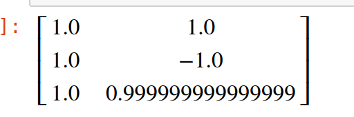
We then invert F by applying the pseudo inverse operation, to obtain F^-1 also known as the control allocation matrix

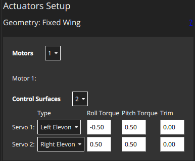
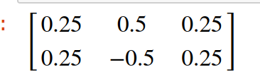
The values which you input into QGC, is the elements of the control effectiveness matrix for each deflection.

Thus the values your enter into roll, pitch and yaw, describes how effective that control surface is to influence that axis of the vehicle.

However, the important thing to remember is that the control effectiveness matrix is normalised. This usually means, that each deflection contribution in the various direction (roll, pitch, yaw) is normalised to the deflection which provides the larges torque in that axis.

Example:

You have a left elevator and right elevator. The left elevator is twice as far from the CoG as that of the right elevator. That means the torque which the left elevator will generate is twice as large. Lets say the left elevator generate 0.1 Nm per deflection angle, which means your right elevator generates 0.05 Nm per deflection angle. This means the right elevator has a effectiveness value of 0.5 and the left an effectiveness of 1.0.

This value does not mean that the control surface is effective enough to control the vehicle, but rather just a normalized value with respect to the other control surfaces which generates torques in that direction.

The amount the control surface deflect will be a linear weighted sum of the various control surfaces that can contribute to the torque being requested by the controllers. Thus the normalised value in the effectiveness matrix does tell you about the amount the control surface will deflect compared to that of the other control surfaces but it tells you also about how control surfaces can cancel out dynamics caused by other deflections. So the effectiveness matrix should not be adjusted to obtain full deflection of your ailerons, but rather comes from first principles to obtains the larges rolling torques the combine control surfaces can produce with close to zero other dynamics being generated.

When a controller request only a yaw torque, (zero pitch and zero roll), will result in the control surfaces to deflect to only generate a yawing moment (usually your rudder causes a rolling moment, and thus your ailerons would deflect to combat this rolling moment caused by the deflection of your rudder)

4 Likes

Thank you Henry for this extremely well written explanation! Going further from your comments, I still wonder the following:

  1. The normalized matrix determines the “relative” scale of deflection each actuator will have, but how does the ‘absolute value’ get determined (-1 
 +1 range for elevons for example)?

  2. Regarding what the ‘normalization factor’, I believe the absolute maximum torque that can be generated with combination of ALL actuators will have to equal 1.0 (after being normalized), instead of ‘Biggest torque generatable from any of actuator’. Is this not true?

The second question was raised, as after thinking about why the Flying Wing’s elevons each have +/- 0.5 effectiveness for roll torque (instead of +/- 1.0, or 2.0, etc.), I have concluded that the maximum roll torque that can be generated with those actuators then equal 1.0 (= +1 x +0.5 + (-1) x (-0.5)), which relates back to the first question on how absolute value gets derived.

Would love to hear your thoughts on these two points!

Note: Seems like this issue is related to the normalization situation in PX4’s control allcoation:

The ‘absolute value’ gets determine by implementing the equations which governs how control surface deflections produces torques: Here is example of two elevons producing a pitching torque:

If we replace all the symbols (except for the deflections) and linearise we get the following equations, implemented for roll, pitch and yaw:

So the above is the unnormalised effective matrix for Elevons. Each elevon produce 6.12Nm per radian deflection in roll, 18.99Nm per radian deflection in pitch and 10.969 Nm per deflection in yaw. So this is the absolute value.

We then take the Jacobian and normalise the matrix and get the following:

image

The above elements are which you plug into QGC for roll, pitch, and yaw.

What PX4 then does, it receives this Normalised Effective Matrix, and calculates the inverse, and then also normalises.

The Pseudo inverse for above matrix is: And is known as the Control allocation matrix.
image

And if we normalize we get (This is not necessary how PX4 normalize the Control allocation matrix)

This matrix is multiply by the controllers torque setpoint (P,Q,R)
and results in:

The column vector which this matrix equate is your normalised deflection of your control surfaces. So to answer your 2nd question: From what I can gather you are using the effectiveness matrix to calculate your deflection angle, but it should be your control allocation matrix.

When adjusting both roll and pitch torques from ± 0.5 to ±1.0, wont change anything, because after the normalised effectiveness matrix is inversed (the Pseudo inverse) its gets normalised again, and this will removed that 2 gain value which you multiplied. Its important to note, that I have normalised each axis with the max value in that axis, whereas in PX4 they do it differently.

Another thing to note, is that you can see that its possible to saturate your control surfaces when commanding a full Pitch torque(1) and full roll torque (1) → PX4 does some handling of this, but in general having dedicated control surfaces for each axis, you wont run into this. This will happened when you try to control pitch roll and yaw just with elevons, as with this example.

I dont think I understand your 2nd question, but I do hope I gave more insight into this. And sorry I cant put math equation into this forum so following the math matrices is difficult.

3 Likes