Got it ! Thanks much @Serge : )
Hi,
I am wiring the same circuit on your picture.Does it work on your drone?
TOM
Hello
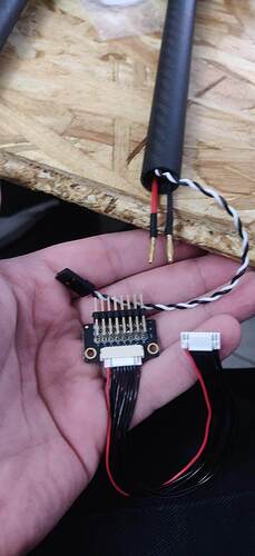
On the photography, the splitter was used for AUX port. But you can use the first Splitter for the ESC.
On The Pixhawk4 , two ports are aviable the first for connect the ESC and the second for AUX (default configuration).
https://docs.px4.io/v1.9.0/en/assembly/quick_start_pixhawk4.html
Serge
All, I am waiting for the common package avalanche from Webshops, preparing in advance to wire up my Hexacopter with Pixhawk-4 and the power module as described in this topic. It would have the advantage of monitoring all current drained from my main battery if I also hookup my ESC´s to this board.
The Documentation on the power module is somewhat limited: it states it can deliver upto 120A. Not sure if that is absolute MAX, or if there is like a peak value not to cross, or if it is even able to cut current when 120A is to be exceeded.
@lloydrayner : I see you hooked up 30A ESC´s, in my case times 6 = 180A. Did you do any stress test on maximum current, and what curren thave you been able to pull out of the Power Module whilst not smoking it ?
grtz
John
All,
I got a decent and clear answer from Holybro on the max. current when distribution to ESC/Motors is done through the PM07 module:
“If the continuous working current for your motor is 30A then you should not choose PM07 but a PDB capable of more than 250A instead.
For the hexacopter, pm07 only allows the continuous working current of each motor to be less than 20A. The boost current of pm07 may reach 180A, but it can only withstand for a short time, pm07 will generate a lot of heat which results in a decrease in reliability.”
grtz
John
Hey,
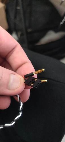
I’m in the same situation as the original poster. The kit I got from holybro is said to be “solder-less”, so the wires that comes out of the ESC have a little connector (the square one of this photo):
Do I really need to cut this connector and solder the white cable to M1, M2, M3, and M4?
Or can I plug them directly on the pixhawk 4 (and use only the PM board for alimentation?)
Or maybe I can use the angled connector on the bottom picture?
Thanks,
Rev
Hi, Sir.
I am a little bit confused by all the online pics. Is that ok either to connect the singal ground wire or not, or doesn’t matter at all?
Hello
I’m trying to build an Airboat with differential thrust
I have:
Pixhawk 4 with the power module
GPS
R12DS Radioink receiver
AT10 Radiolink transmitter
2 80A ECS
2 brushless motors 620KV
I have installed AurduRover/boat
I have connected the ESCs to M1 and M2 in the power module,
however, the M2 (motor 2) is not working
anyone out there that could help me out
Thanks
For ArduPilot help, best to ask at discuss.ardupilot.org
@Rev How did you connect the esc?
@Rev:
I am in the same situation with the same question. Do you have any advice based on what worked for you?
Please provide some details if possible,
Thanks
Bindu
Hey there. I had to plug the wire directly on the power board from the esc (the small rectangle connector). I’ll be able to grab some picture tomorrow if you want 
That would be great, will help me to see how it is done, Thanks in advance,
Bindu
Hi Sir, I am using this PM02 for my F450 Frame with Pixhawk 4. I already soldered my 4 ESCs Back+Red big cables into the PCB bottom board of the frame. Besides, my ESCs have another twisted thin white+black cable which means signal wires(I guess). Because the PM02 doesn’t have a little hole to solder the white signal like the PM07(showed in some pictures above), I just connected my 4 ESC signal wires to the slitter, then connect to the I/O PWM OUT(on the Pixhawk 4) through that 10-to-10 pin wires( as you described “closed to M4)”. So, I am wondering if it is a correct connection(no other step or connection needed) that the power from the battery could make 4 motors rotate? The reason I asked this is that when I do some setup on Ardupilot, I got stuck at the “ESC calibration” step, which prevented me from making all 4 motors rotate. When I plugged the battery in, all motors are beeping which means the PCB should work. That makes me think the above connection might be wrong or lack of connection. If you know what could be a reason and how to solve it, please help. I would appreciate that a lot. Thank you.
Hi sir! I have questions to ask. First i have a 4-in-1 ESC ( Dshot1200- mamba stack as pictured). What can i do to connect it to a Pixhawk 4. How can i powered the ESC because im using a 6s battery to power up my motors. Is that necessary to power up both esc and pixhawk with 2 dedicated LIPOs or i can sold my ESC to 1 of the output power of the Power Management Board. Is that enough to power all four motors of mine. The second is that is there any caution should i take when config it through mission planer app?. Or Pixhawk will recognize ESC as normal?
Hi did the spliiter work for the ESCs’ signal wires?
Thank you in advance
Hey.
I see this is an old topic, but with valid question.
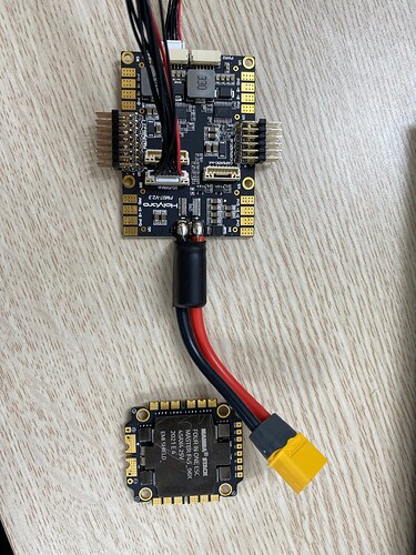
I’d like to comment on that sketchy image @lloydrayner posted. The ground cable (obviously black) from ESC, that goes with a signal cable (white / yellow) MUST be connected to ground on ESC. And there are also two other recommendations - it should be as short as possible, and it would be best to twist it (like in ethernet, twisted-pair). In addition of connected ground wire, that will limit any noises / spikes that induct in signal wire. That it is very important to connect GND wire that goes in pair with signal.
Using GND of power (thick cables) will not make it’s job in terms of cancelling / reducing spikes.
That are my five cents ![]()
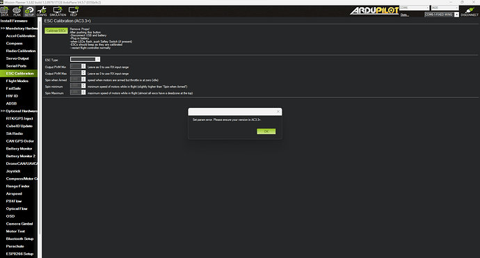
Hello everyone! We have a situation with our v-tail winged plane design, where we can’t do the ESC calibration, as in when directly connect ESC to receiver we can spin the motor thru transmitter, but when connect ESC to pixhawk (Main out1), motor doesn’t spin and ESC calibration fails (w actually get an error: Set param error, see atttached). What are we possibly missing?
This is PX4, please consult in Ardupilot Forum.


