MindRacer is another attempt towards a more modularized UAV system in miniature/nano size range, based on PX4 stack.
Racing is fun and exciting, soldering/unsoldering/cutting and wiring the mess are pain. One of MindRacer’s design purposes is trying to implement a structural hardware, as well as quick assemble/release inter-components interfaces.
For a long time PX4 has been regarded as too ‘heavy’ for a racing system. We try to demonstrate here that a very tidy, modularized racing system architecture can be built upon PX4 platform. It should be regarded as another practice of PX4 hardware implementation for racers and miniature systems, and we hope it is the best so far. We publish the designs here so that these efforts can be seen and discussed in a more wide range.
Racing seems to be a really interesting application full of paradox, as it has extreme limitations on weight and dimension, but still eagerly desiring for highly modularized components. We have to be very carefully balanced in between.
Before MindRacer we have seen and also tried many different designs on modularity, some of them led to very clumsy results, and some eventually become part of MindRacer. Among them were the WEP interface and SEP interface.
The WEP (Wiring Elimination Port) interface
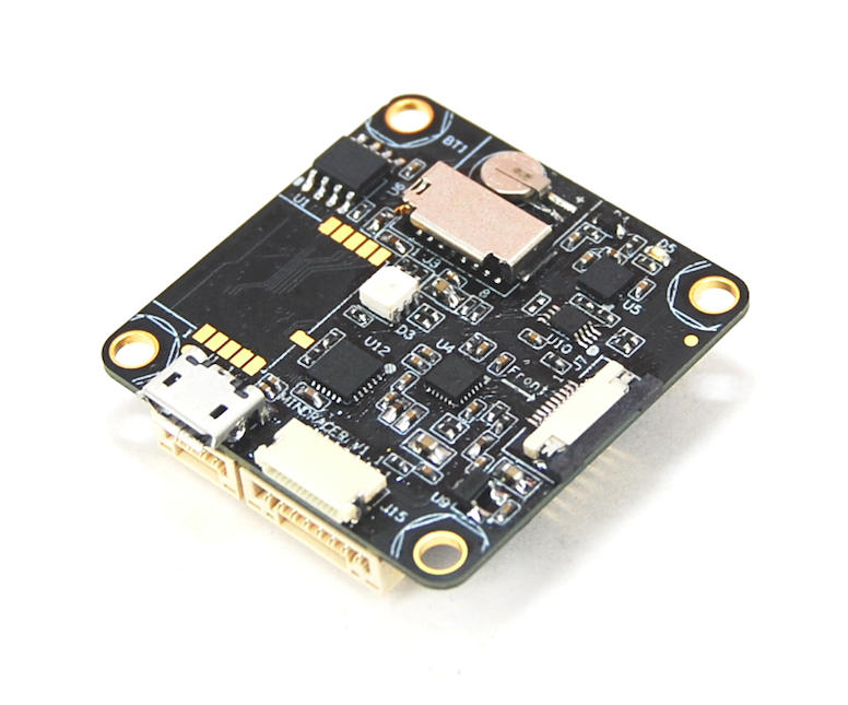
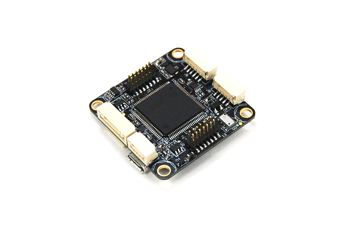
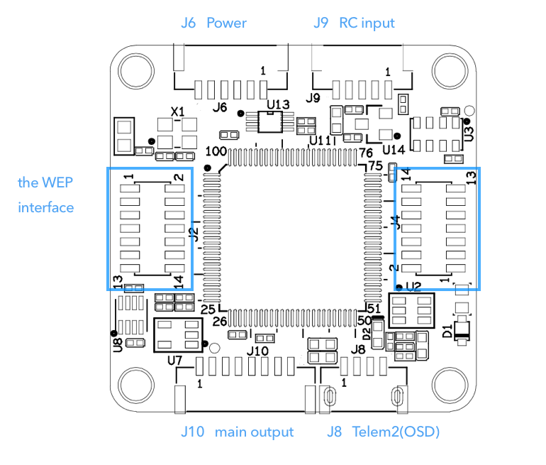
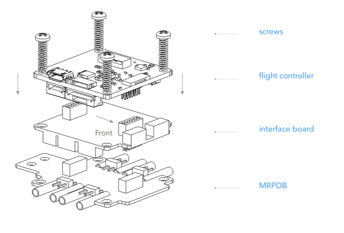
MindRacer mainboard is defined to be a minimum piece of gear that can barely meet the demands of racing matches, nothing more and nothing less. This formed the MindRacer’s hardware boundary of functions, as shown in Fig.3. Functional ports J6, J8, J9, J10 are exposed on mainboard, as these are what pilots need in any regular matches. All other ports, like I2C, GPS uart, etc., are extended through the WEP interface - dual 1.27mm pitch 2x7 pin headers board to board interface (Fig.2 and Fig.3).
The WEP interface results in a very tidy stackable structure for racing drone/small UAV assemble. The pattern of WEP stack defines how the boards are stacked together when in a compact space like racing frame. These may includes radio transceivers, cameras etc.
The pattern is every expansion board have a pair of female headers for receptacle on top side, and a pair of pin headers to led out.
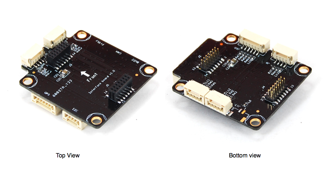
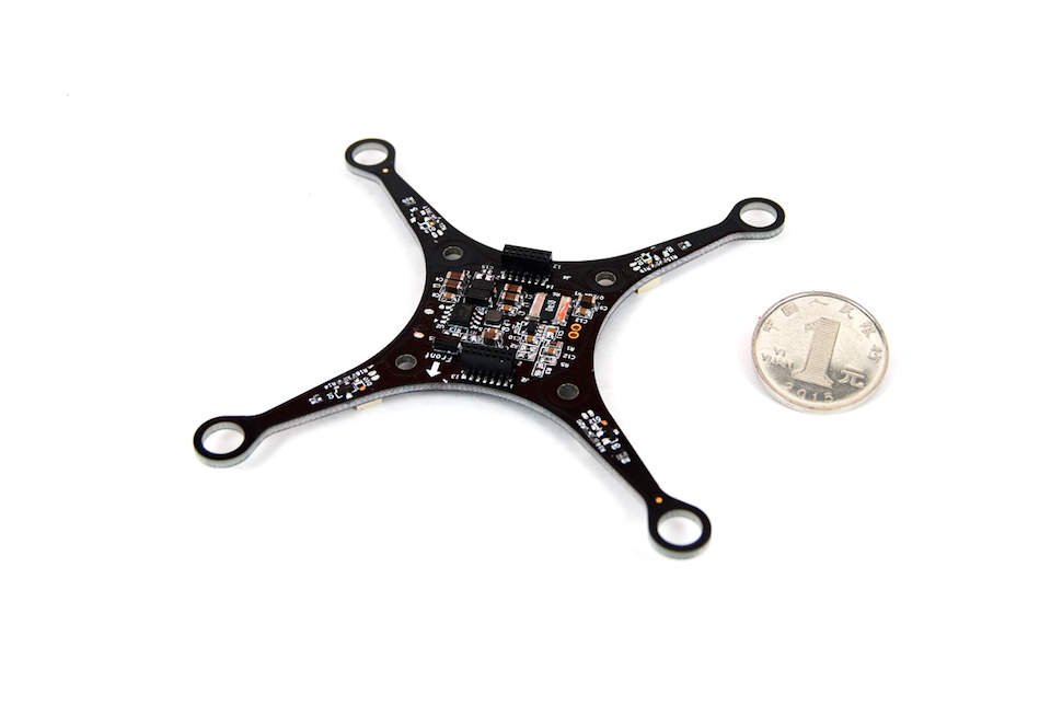
The interface board is a good example following this pattern. In case the pilots need more ports, they can be led out through an interface board. Fig.4 shows an interface board with almost all interfaces available including GPS/I2C/CAN/spare UART/extra USB/BUZZ, etc.
Fig. 4 The interface board following WEP stack pattern (Weight: 5g)
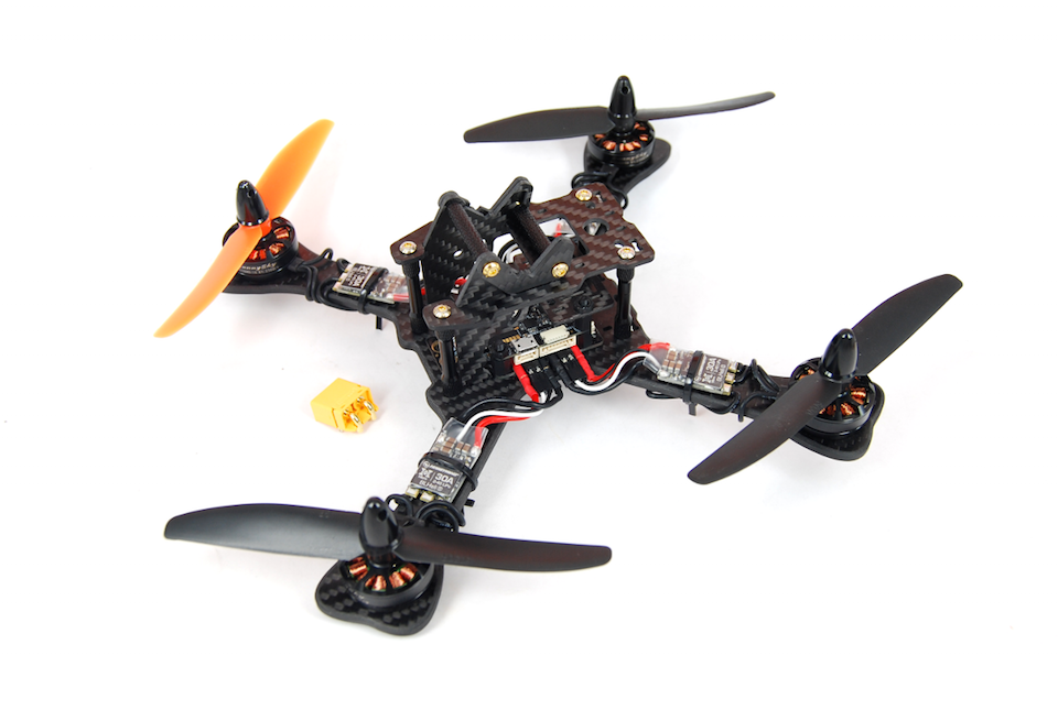
Following the same pattern it can be stacked over the MRPDB and easily mounted together with MindRacer.
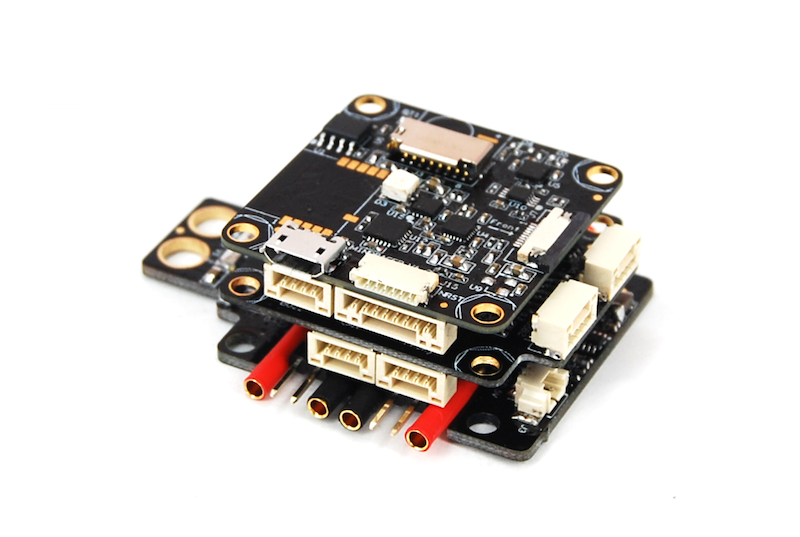
Fig.5 stacking MindRacer, interface board, and MRPDB together
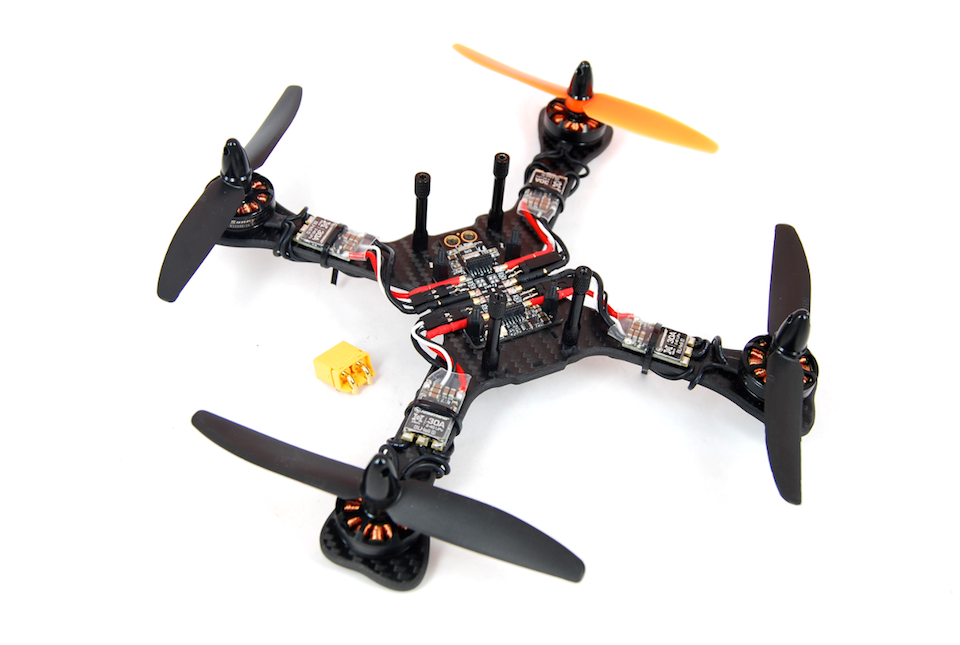
The SEP (Soldering Elimination Port) interface, and a real design case: MRPDB.
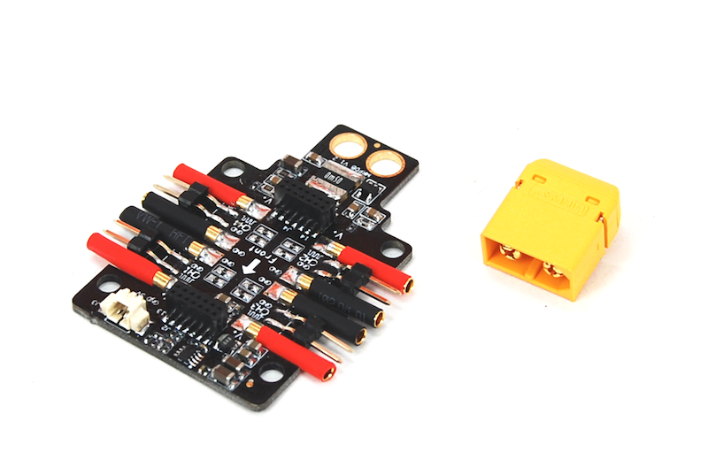
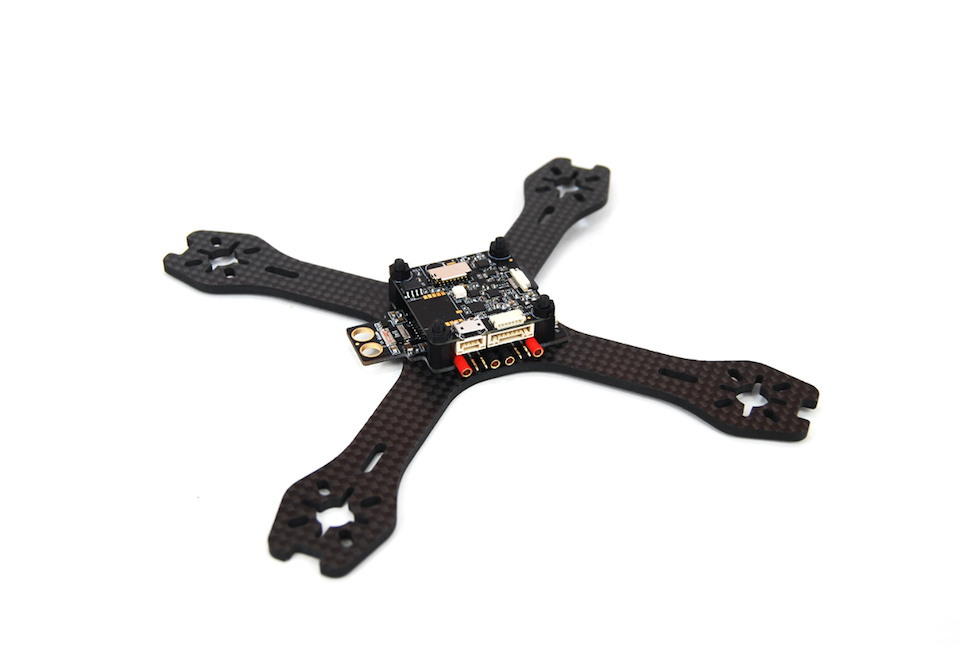
Although you can use any other PDB together with MindRacer, MRPDB is more recommended. The MRPDB (Specification) is re-designed of PX4 PDB under this pattern. The MRPDB is designed to be a soldering-free but plug-n-play PDB. The MindRacer mainboard + MRPDB is a minimum but complete system for a racing drone.
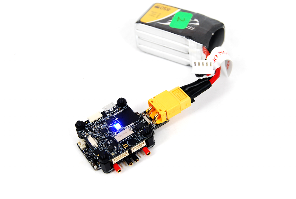
Fig.8 MindRacer + MRPDB, minimum complete racing core
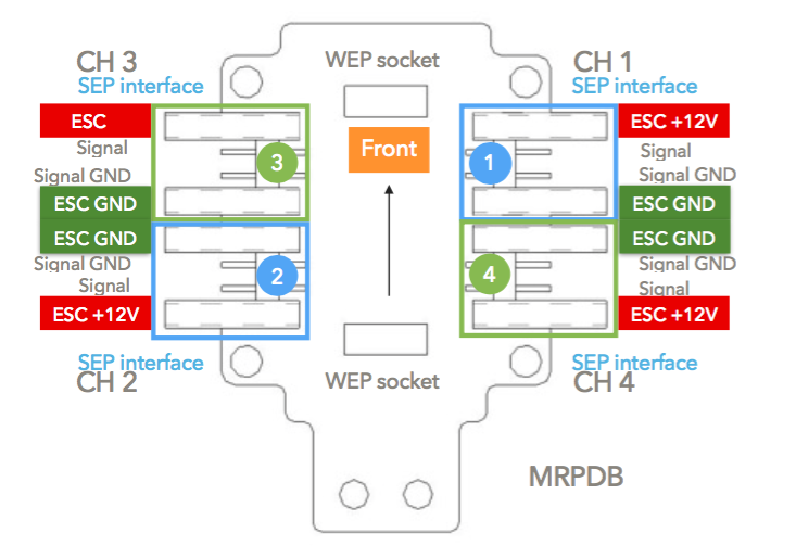
In order to support soldering-free and quick replacement, MRPDB uses 2 bullet female headers for ESC power connection, and 2 2.54mm pin headers as PWM signal input. 2 female bullet headers and 2 2.54mm pin headers together makes one ESC output port (the Soldering Elimination Port - SEP interface). Total 4 SEP are laid on MRPDB. The PWM outputs from the mainboard are routed to its SEP interface through MRPDB’s WEP interface. The ports are numbered according to PX4 motor mapping.
The mainboard is powered through the WEP directly, including voltage and current sensor input. To convenient assemble and design of extension boards both pin header has power input pins.
As a result, No wiring needed from the main board anymore.
The connection between MRPDB and ESC/motors becomes plug and play. No soldering work is needed when replacing or switching ESCs. This becomes extremely handy and a process of pleasure during a real match in field.
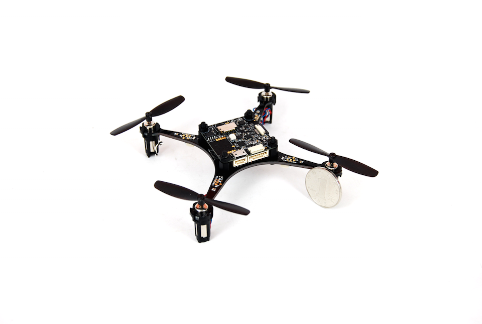
MindRacer has also been mounted on a nano frame, powered by Coreless DC motors.
Configuration:
110mm diagonal PCB frame
4 x Coreless DC motors
3.7v 1s 550mah battery
The above building cases have proven this stacking pattern are quite feasible and applicable on small/nano size frames. And more specifically, the WEP interface and the fishbone on PDB works actually quite well during the assemble and test flights. We will be interested to see how this design can be adaptive to different kinds of cases, and you are very welcome to create any board that can stack together with it!
PX4 is already the most powerful flight stack. To be a great racer, there still a lot to be simplified and lot to be enhanced. We hope MindRacer as one of the attempts is just a start and more will follow. @LorenzMeier@PKocmoud@Mark_Whitehorn
Awesome platform! Do you have the ability to make a few of those available to the development community? (I have 2 or 3 developers in mind who would benefit and can contribute tuning).
What would be really great would be to have a RTF option available.
@LorenzMeier
thanks.
I will be glad to provide some MindRacer boards for tuning. I just sent you an email. Please let me know the details so i can arrange the shipment asap.
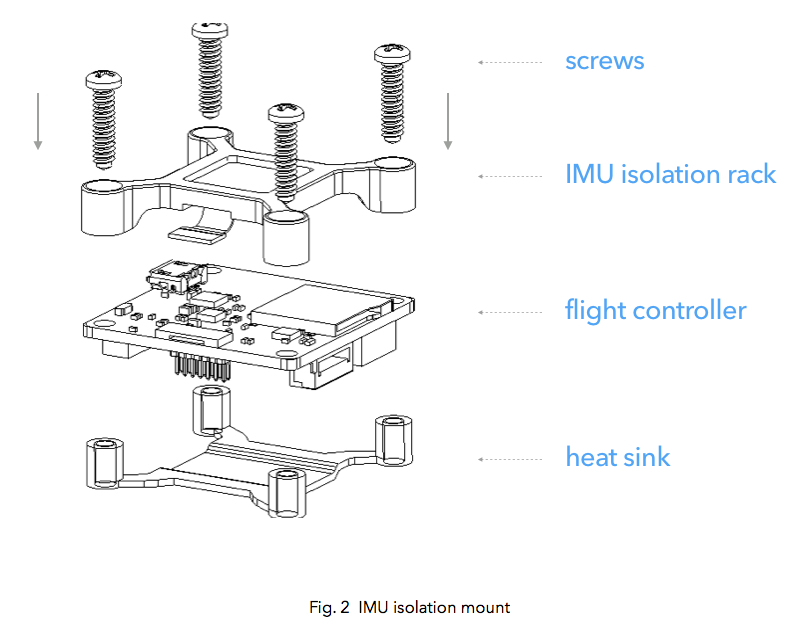
There is a consideration for that. Usually for racing IMU/vibration isolation is not used, however we reserved the IMU isolation interface in mindracer main board in case pilots will need it in other applications.
there is 2 ways to isolate vibration:
mount the mindracer and MRPDB(or a heat sink) on a foam pad, that is the regular solution as others.
use Mindracer’s on board IMU isolation interface to mount an redundant/independent IMU board, as in following figure.
You can get more details about mounting isolated IMU board in MindRacer’s user guide document (link on top).
MindRacer runs PX4 stack so it supports redundant/independent IMU board. This IMU board will also be available soon as a standard component that can be stacked together with MindRacer and other components.
Or, you can also make your own isolated IMU board following this pattern which meets your specific needs.
@rolandash Great Job! I really like the idea of stackable flight controllers! This is must have for racers.
From the photos provided I have several comments/concerns as for fitting the “racer” needs.
RTC battery holder doesn’t look very secure and will go off after significant crashes (which happen all the time during racing and practicing).
MRPDB uses connectors instead of solder pads and they stick out of the board. So even a mild side crash will break these connectors off. I have talked to several pro racers in the area and they all prefer solder pads for everything and no connectors on the board at all because of various reasons. Reason number 1 is that connectors go loose after some time and reliable on vibrating drone and during crazy maneuvers. Reason 2 is that its easy so short circuit unused connectors easily after crash/land into the wet grass. Reason 3 it’s much easier to break off connector than solder pad.
on MRPDB you don’t really need ESC signal and power ground, only power ground is enough. So total 3 wires from ESC 2 power cables and 1 signal.
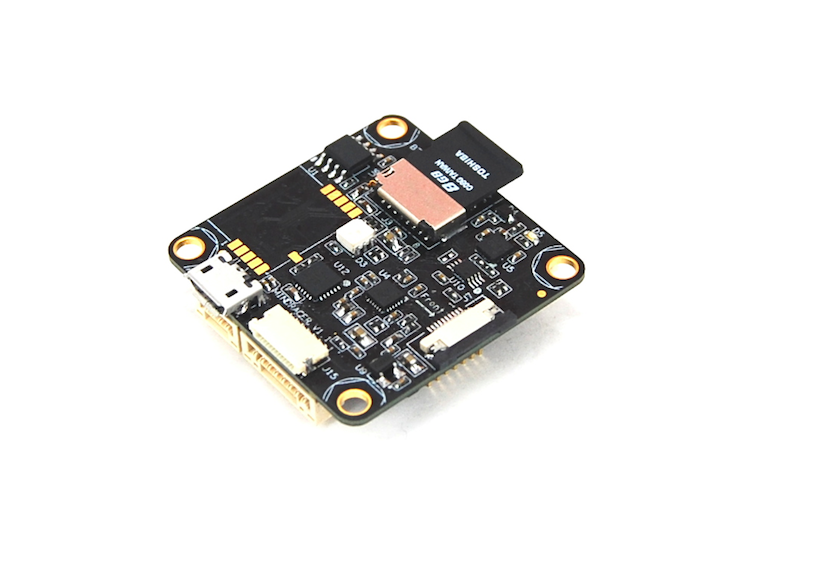
There are no pictures of main board with microSD card. Does it stick out of the board?
I already have a wish list for stackable boards:
PDB that has 12v SBEC for powering VTX and solder pads instead of connectors
@anton-matosov
thank you, i am glad that you like it, let’s just make PX4 stackable
Looks that you are a good racer as your comments are quite professional and get the points.
I will not worry too much about the RTC battery, as this design inherited from MindPX, which experienced lot of severity crashes during various flight tests and survived. The battery in racer is even smaller and lighter, and the soldering pads are long enough to hold it tight. I can’t say it can never go off but the chances are very small.
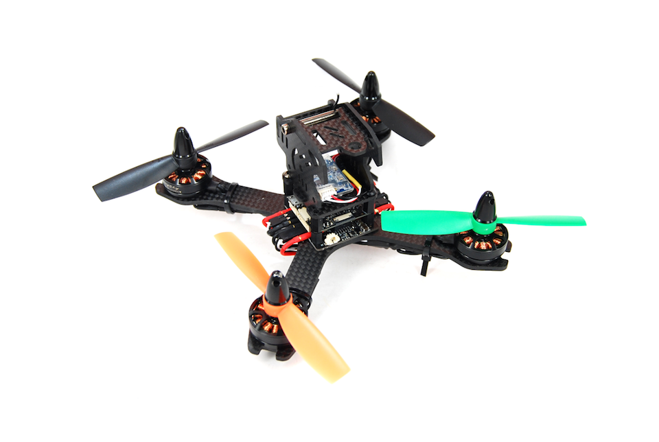
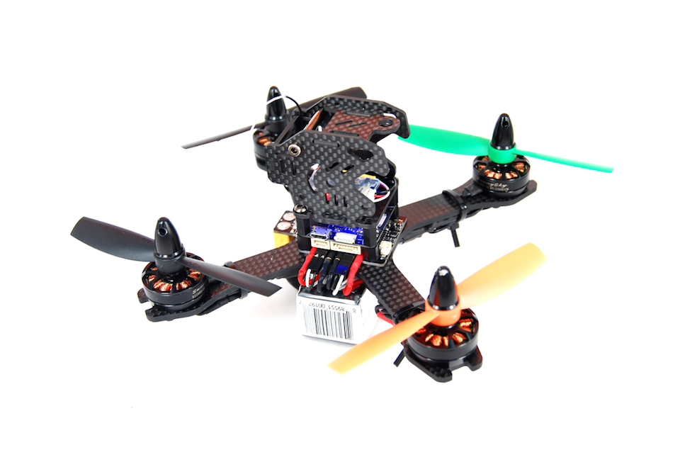
You hit the right point and i gonna say a lot about this topic. You are correct, some pro racers does prefer soldering than connectors, and i did heard them talking the same reasons you list here. However, why we still go for the connector design is because things all have pros/cons and we need to balance, and i believe these problems have ways to solve. If you look into the photos i posted above of the small X racing frame you can see these connectors are actually hidden in the central part of the frame and under the protection of the motor arms. When crash into anything from side the first contact will be the 2 hard side arms and unless it accidentally hit into a sharp angle very less chance that these connectors can be directly impacted. In a bigger H or X frame these connectors will be even nicely shielded by the body frame. Again i am not saying this would never happen, but the same chance may happen to any kind of design during a perfect crash. The tradeoff we take at this point is for those people who really hates soldering or not good at soldering skill. including me. I personally have experienced too much frustrated time that have to interrupt the flights just for some cable been ripped off from the board during a crash and i can not fixed it just because i did not carry an iron with me or the soldering is too difficult for me. And i pretty sure there are lots of people like me out there. The name of this interface, ‘Soldering elimination port’, basically already showing my attitude to this problem.
I have to admit that bullet headers are not the best connector for this purpose, but before we have a perfect choice, the reasons you listed do have solutions.
Reason 1 actually can have ways to solve it or work around - replace the bullet headers regularly. That is why MRPDB comes with some free bullet headers. It is easy to have a check on the headers as these are all one click thing - if you feel it loose then replace it, and you only need to do that monthly or quarterly, instead of carry an iron every time you fly. To prevent from vibration during flight, you may notice that these connectors are purposely placed close to each other, thus increased the friction when all plugged so it is expecting to be quite solid under vibration.
Reason 2 can also be solved. as you can see in photos all connectors are already protected by heat shrinkable tubing, not only prevent short circuit, but also to prevent miss insertion by using different colors. And i think the wet condition will affect all exposed components.
Reason 3 can be YES or NO. Soldering is not that solid as one think. I am not good at soldering but do tested a lot of boards. For one with bad soldering skill, or a false welding, the cable will go off quite often, especially in winter. Even soldering has no problem, long time vibration, bend/stretch may make the contact problematic. A crash can also easily rip cables off from the board and even damage the board, but a connector may still have the chance can be just re-pluged in.
In the end, I am not expecting to persuade all with above words, as these i think are really personal favors. If one really dislike the connectors. remove them from PDB and solder the cables on pads will just fix everything! MRPDB is open sourced so ultimately, one can also make their own stackable PDB to adapt to different frame shapes.
I actually had a 3 wire version of the PDB, which i guess you may dislike more:-)
But canceled the design to 4 wire version as: 1) in order to increase the friction on vibration 2) 2x2.54mm pin header will be more easier for ESC calibration
here is a photo with TF card. yes it does partly stretch out the board edge.
I understand you may worry the card maybe smashed away when crash. it’s partly because of the PCB layout density. And, as existing TF slots has no way to prevent that happen during a crash unless add an enclosure for it - which we do not want to do it during racing. use a small pcs of tape instead can do the job.
I share your wish list, and i actually welcome anyone join us to make them together. Except that i am not sure about a 2 or 4 in 1 ESC as 1) i do not want replace all ESCs just because one of them is burn. 2) The heat 4 ESC generated is not good for flight controller. I still believe ESC should stay where the coolest place is.
Thanks for the detailed reply.
I totally agree that good quality connectors are much better then bad quality soldering.
My point was about pro racers, they do not trust connectors at all. The rest is pretty much ok with that.
I like the 3 wire version of the PDB. If you take off the bullet connectors it becomes a good board with solder pads =)
TF card sticks dangerously too far. It will rip off with the slot all together during the crash.
I managed to rip off the FrSky port from pixracer entirely and ESP8266 port partially. So from my personal experience anything that sticks out of the board can and will be teared off