I’m putting together a small telemetry board using esp8266 Wifi plus a LoRa radio. The Wifi is high bandwidth and relatively short range and the LoRa radio supports low-bandwidth long range telemetry. In my case this is for a boat, but it could be used on any px4 set-up really. I’m wondering how to best connect this to a pixracer (or pixhawk).
The main issue is the bandwidth difference between Wifi and LoRa. For the latter expect 10kbps (ten kilobits per second) max and down to 1kbps for long range (could go lower, but then it’s probably only useful for very basic GPS and attitude info).
The first question is how to connect such a board to a pixracer. I want to use “raw” sx1278 LoRa modules, not ones that have a serial interface. The sx1278 uses an SPI interface and there is no way to connect an external SPI device to a pixracer, so the esp8266 will have to control the LoRa radio (there’s software out there and I’m very familiar with driving the LoRa chips).
The second question is how to control what goes over the LoRa link. The esp8266 only has a single usable UART RX, so it’s not practical to connect it to a second telemetry port which could be configured for a lower data rate.
make the split in the esp8266: it could be configured with a priority order of mavlink message types and it fills the slow LoRa link with the highest priority messages that are being sent over wifi. Or a slightly different scheme could be used that assigns packet rate ratios to various message types, e.g., for every 10 GPS position packets send one mission status packet.
make the esp8266 software dynamically send PX4 commands to change the data rates depending on whether it has wifi connectivity or only LoRa. I don’t know whether this is possible or not, but it sounds tricky, specially the hand-offs could have significant time gaps.
multiplex the serial port to the esp8266 to carry two logical telemetry channels, one for Wifi the other for LoRa. Each packet could be prefixed with a channel byte. Sounds like this could take quite some code and it makes the telemetry port protocol non-standard, non-compatible.
A nice thing about having an esp8266+LoRa board is that on the QGC end it can be used as a LoRa to Wifi bridge, so two board with different software can be used to make a complete solution.
I would very much appreciate any input here! I am planning to fab boards at osh park and would make the designs available if there is interest.
Thanks for pointing out the MindRacer, I hadn’t seen that. Looks like it has all the features I need from the Pixracer and perhaps the expansion would be easier, but on the other hand the expansion connectors use up quite some space.
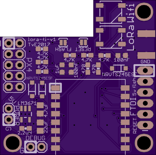
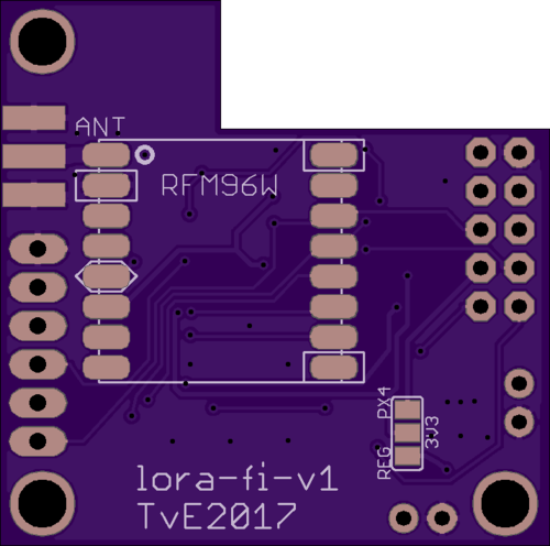
I spent the day putting together a PCB. 36mm x 36mm to fit on top of a pixracer with a connector to fit into the pixracer’s esp-01 socket. The board contains:
esp8266 using either an esp-12 or a esp-07 module (built-in vs ext antenna), in both cases the esp module sticks over the edge
HopeRF rfm96/rfm98 LoRa module with board-edge SMA connector
two RGB LEDs to indicate Wifi and LoRa status / activity
cut-out to allow vertical PWM connectors on the pixracer and to allow dense stacking
switching regulator with jumper to select between using the pixracer’s LDO or the switching reg (needs 5v input)
FTDI connector for initial flashing and debug output gpio2/tx2 connector
Now wait 2 weeks to get PCBs back… The mavesp firmware should work with just some minor tweaks to adjust pins and then the fun of jamming some LoRa code in will begin. Assuming the PCBs work, of course…
For integration I can see the appeal of combining LoRa + esp8266 on the same serial, but on most boards we have several serial ports available and it will make the software side much easier. The pixracer has 3 telem ports.
Yup. I guess the alternative is to have esp8266 for Wifi, and then some small ARM chip and sx1276/sx1278 for LoRa. These could be on one board or they could be on two boards. Mhhh.
I haven’t. To be honest, I’ve used the esp8266 a lot and am very familiar with it, plus there’s mavesp ready to go… I started on the esp8266 when it just came out and suffered through all the pains WRT bad docs, bad SDK, bugs, etc. When the esp32 came out I decided I wasn’t going to deal with the esp32 until I either desperately needed it or the bugs were worked out. I have the feeling that for this project the esp8266 is going to work just fine :-).
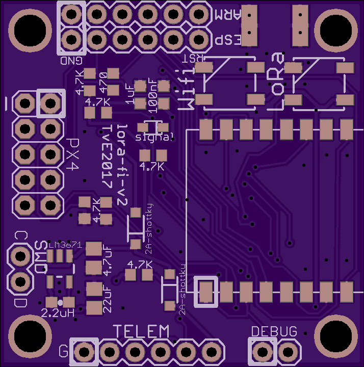
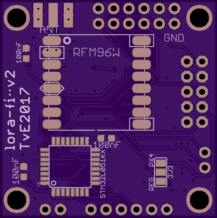
I did take dagar’s comment to heart and have ripped up the PCB layout I had and dropped an stm32 in there to talk to a telemetry port on the pixracer and to the LoRa radio. This way the Wifi part and the LoRa parts are completely independent (just on one PCB for convenience). At the ground station it should be possible to cross-connect the two ports to make a LoRa-Wifi gateway.
Well actually i am more favor of multiplex version, though this may complex software a bit.
I am adding multiplex of Mavlinks into MindRacer/PX4, targeting at different radios though . If we looks this forward longer as when radio peripherals increases, it will be not possible to connect them all through seperate telemetry ports. Having a single access point for all radios will become necessary. @dagar
I suppose that could make sense in some situations. I wasn’t sure about things like flow control and ramifications for mavlink in that situation. Some of these are available SPI as well?
Flow control and rate matching are indeed needs to be considered, it will require some intelligence inside radio module in that case. Can be achieved through few extensions of mavlink i think.
Of course, in different use cases seperate telemetry radio is also not a bad choice. A hybrid model is probably the best for most applications.
PS: I recalled that months ago you mentioned the flow control issue on MindRacer so the new release is a good time to improve it. I don’t want to interrupt this post so probably in another thread.
In my PCB I hooked up the esp8266_RTS and esp8266_CTS pins that are on the pixracer, but searching through the code I have the feeling that flow control is not actually enabled in the PX4 firmware, is that correct?
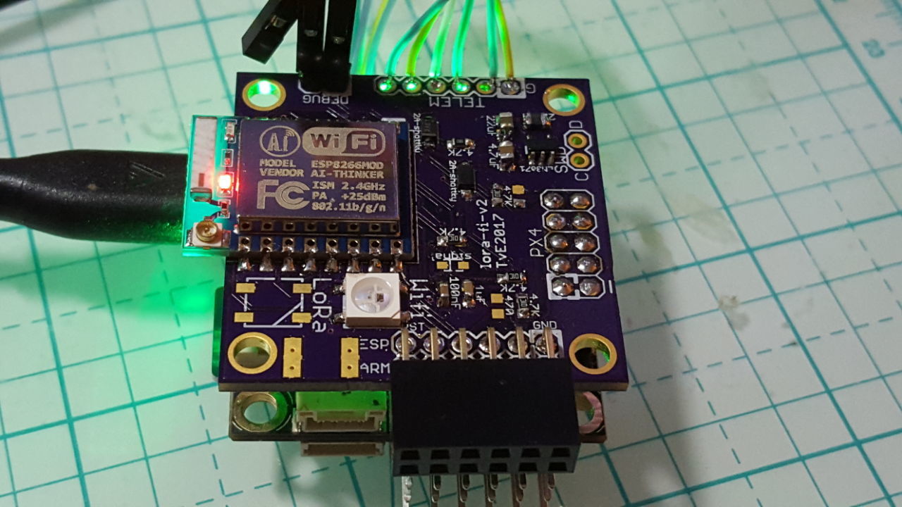
First success: the esp8266 part of the board works! I have not populated the LoRa stuff yet. That will probably take some time…
If anyone is interested in schematics, lemme know.
In the photos, the lora-fi PCB stacks on top of the pixracer’s esp8266 connector, it also connects to telemetry port 2 for LoRa data and 5v power. The double-row female connector sitting above the pixracer’s PWM ports has the FTDI ports to program the esp8266 and the ARM processor (for LoRa). There’s a switching Vreg to generate 3.3v (instead of the pixracer’s linear Vreg), and an LED for status indication (next thing to add to mavesp). The debug connector has the esp8266’s uart2 debug output.