Hi, I recently purchased the Pixhawk 4 and I am unsure how exactly the wiring works. The explain in the user guide gives just a single picture:
The part with how the 5V BEC connects to the LiPo battery confuses me… I don’t understand how the two should connect. I have the battery, the BEC, and the PMB below:
So it seems I need to solder the 5V BEC to the two pins displayed, but how does the battery power both the BEC and the PMB? Do I need to split the signal coming out of the battery so that it can somehow go to both at once?
The two thin red and black wires from the BEC have to connect to the red and black wires coning from the LiPo battery. The easiest way to do this: Solder the red and black wires from the BEC directly to the solder pads on the board where the heavy wire from the battery cable is soldered.
There also may be adapters like the one in the photo with the blue and yellow connectors, that have another set of wires coming off to a separate connector for attaching the BEC.
I’m not sure what you mean by “directly to the solder pads on the board where the heavy wire from the battery cable is soldered”. Which wire is the heavy wire and how exactly would the BEC be attached?
I think I get what you’re saying about the adapters… would something like this work?
I can envision cutting one of the connectors off and soldering the BEC to the red and black cords while the other half connects to the PMB.
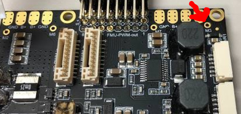
Would anyone here be able to help with a different sort of problem? I’ve posted a picture below showing the soldering that I had completed, but the ESC (the one on the left) overheated so much that its black wire detached from the solder pad (see the ESC’s top left corner). The ESC is a BLHeli 30A (BEC 2a 5v, LiPo 2s-4s) and I was using a 3 cell LiPo battery. Any ideas what might have gone wrong here?
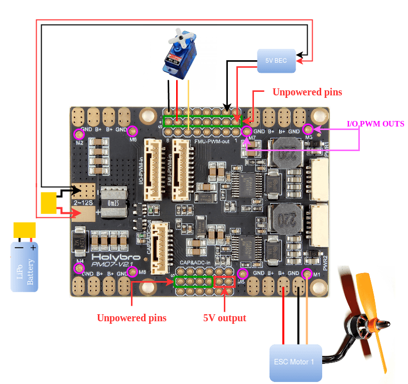
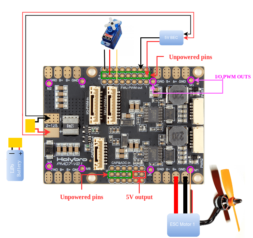
I’m not sure what type of vehicle you are trying to create, but assuming it’s a basic quad, maybe this picture will help. The thick red and black wire that came loose should be soldered to the pads where you soldered the thin red and black wires. For basic functionality you can leave the thin red and black wires disconnected. By soldering the thin black wire to a common ground on the board, you should get less noise in your esc signal wire (thin yellow wire). Some newer esc’s have just the signal wire, some have just a black and white or yellow (ground and signal) wire like the picture at the bottom.
Yes, it does seem like the thick red and black wires need to go to the B+ and GND pads. I actually just confirmed the same solution from another source, so I’m going to give the re-soldering a shot later today and see if I can get this flight controller going.
Unfortunately, my soldering iron was not able to get the big red and black wires to attach, and the Power Management Board was accidentally damaged… I’d probably have to buy a new one if I wanted to continue. This project probably wasn’t a good idea for a beginner.
Lots of words and diagrams. Let me try another route: I hope this sums it up.
BEC (Battery Eliminator Circuit) - provides 5V power, if you need extra power at 5V, or there is no other source, or you want a backup 5V. If you have a power module, this may be unnecessary.
ESC (Electronic Speed Controller) used for driving 3 wire brushless motor. Needs beefy + and - power in, and a control line in from a flight controller, or straight from a radio receiver channel if you were connecting just to a single propellor aircraft motor. An ESC may have a 5V output line (a BEC within the ESC). Thin wire.
Hi Ocularmagic,
I have newer esc’s that have black and white (ground and signal) wire. Do you know how to wire on PMB?
I’m not sure how to solder down two wire on one place Mx?