I have recently purchased one of the Holybro Pixhawk 4 and could use some help in clarifying how to connect the ESC’s (8 in total).
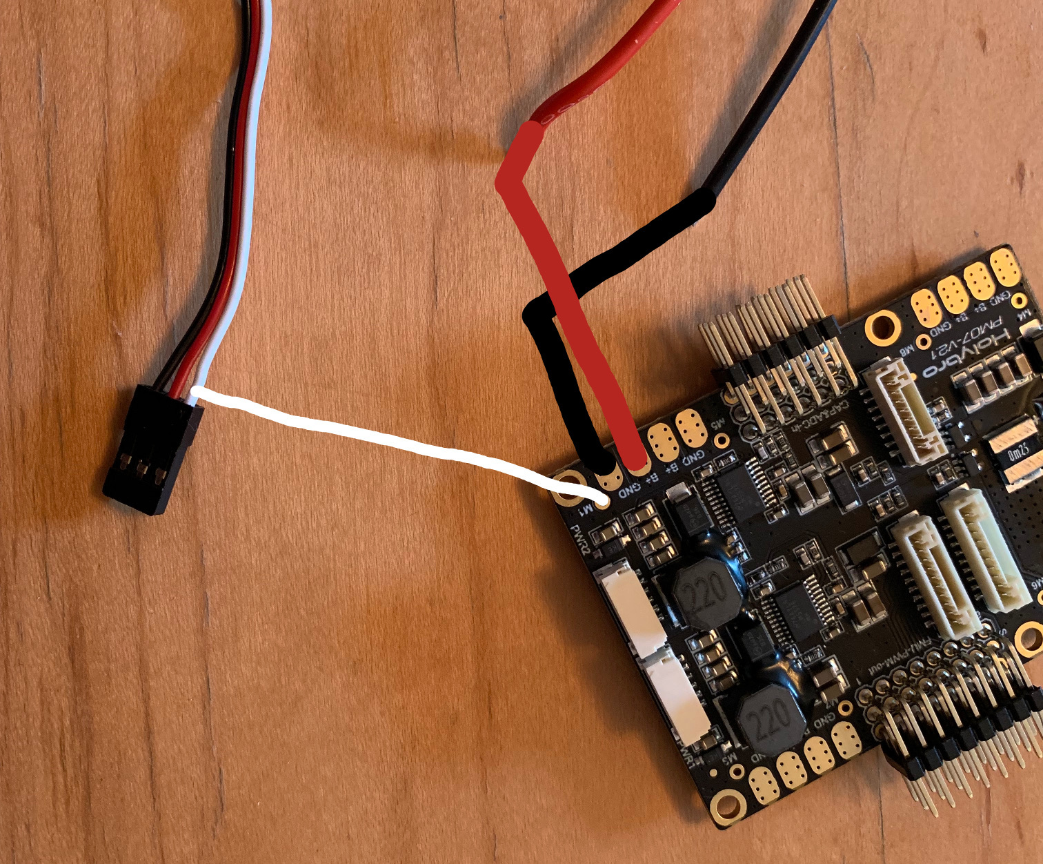
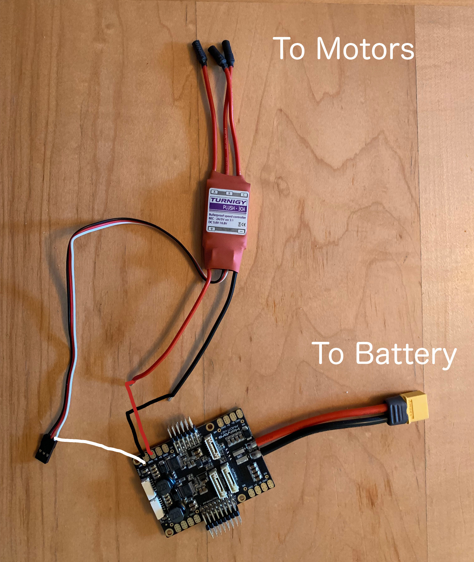
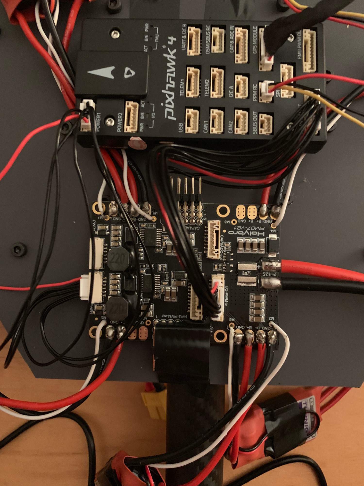
Reading the user guide I believe that I am to take the Red and Black power wires from the ESC and connect to B+ and GND on the Pixhawk 4 Power Board then take the White wire from the ESC and connect to M1 on the power board. (as per the image below). The thin red and black wires from the ESC are not needed.
Does anyone know if this is correct?
I assume all power will come from the battery, through the power board and into the ESCs so no additional wiring is required, is this right?
Hello
I used this method.
It is interesting if ESCs are powered by Power management board.
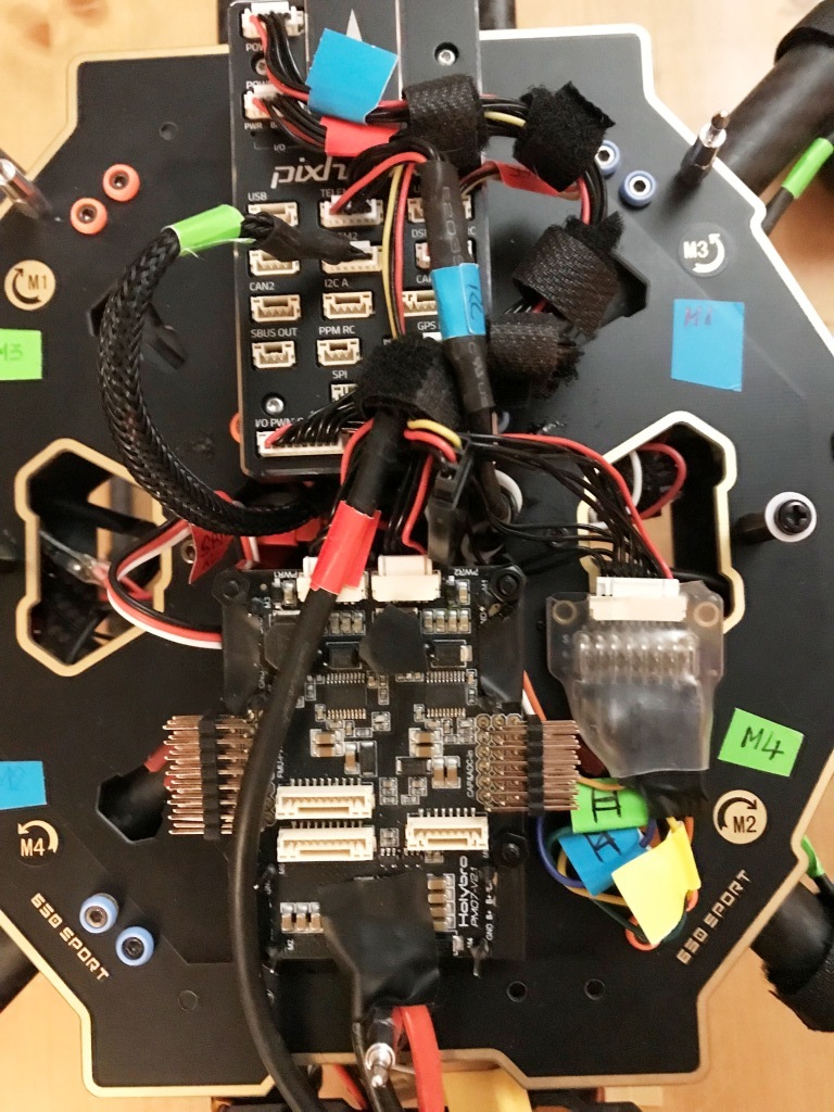
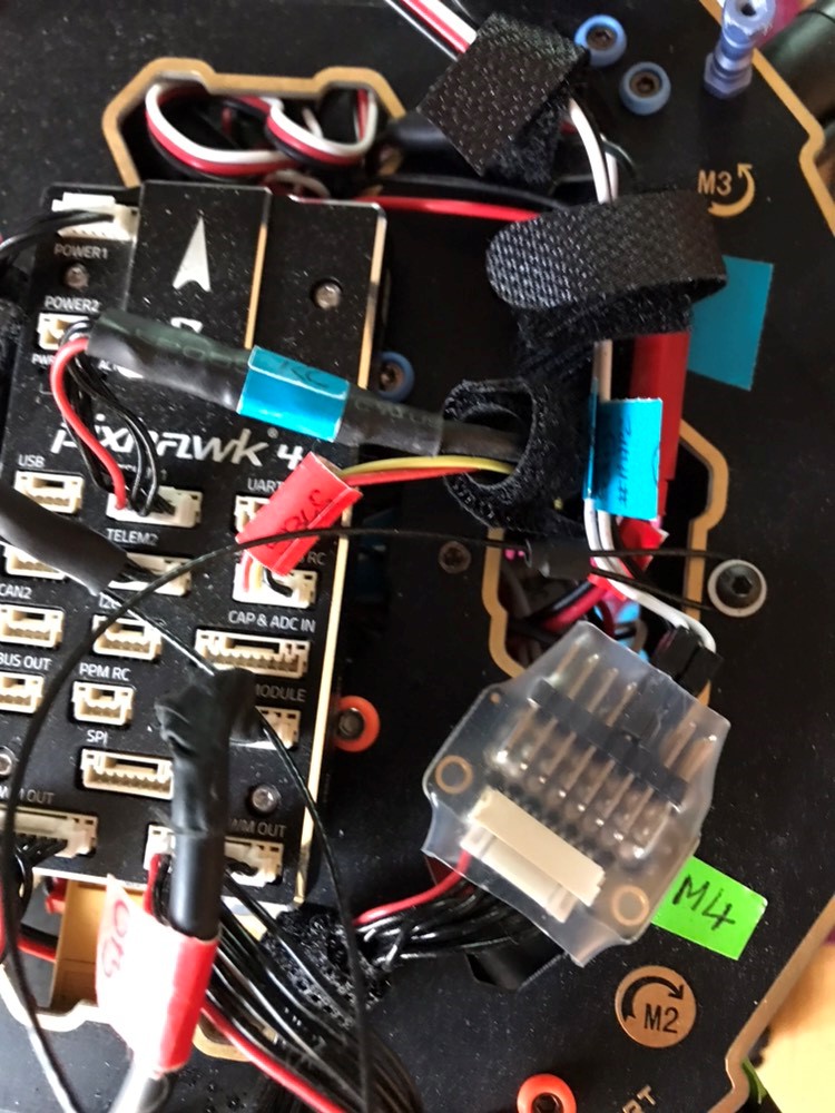
You can also connect directly the “ESC” on splitter board wich it is content in the package (See close M4).
This second case is useful, if the ESC are powerded by the main board of the frame (example : Tarot 650 Sport).
I preferd isolated the connectors under protection thermoretractable.
I think he mean to say it’s Good way if you connect the ESC to power management board because that’s why they are designed for. If the ESC need allot of power so better to leave it to distribution board.
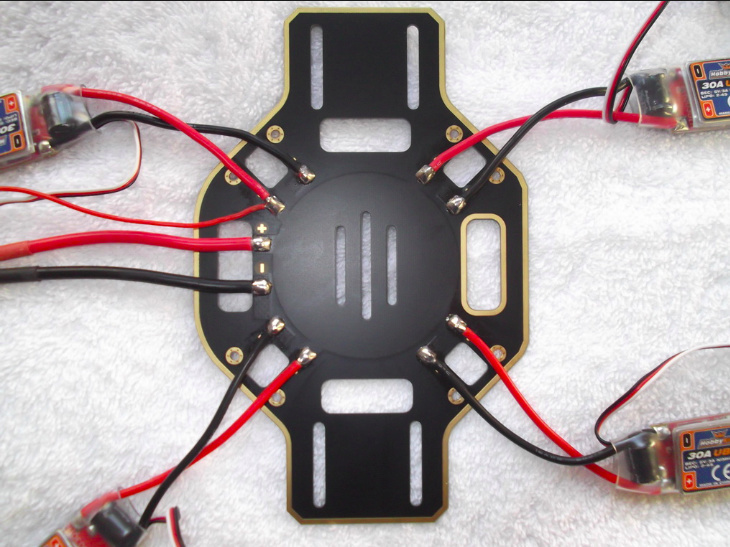
On some Frame, the ESC could be connected directly and for Basic use. For example, the Tarot 650 Sport and DJI F450, the ESC (PWR ) could be solder on the main board . In this case is more simple and clean(my point of view). If your frame have not integrated the power distribution, the Power management seems me board is usefull.
I think remove this Power management Holybro (two electrical source) but only one battery on my Quadcopter by one more simple.
Hello !
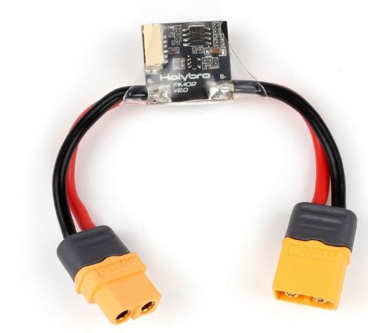
I am using DJI F450. I believe I can use the power distribution of the frame to power the ESCs (see image below). Will I be required to use the power distribution board of Pixhawk 4 ?
For each ESC, the power (6S for Tarot 4114, for my drone) is connected directly on battery.
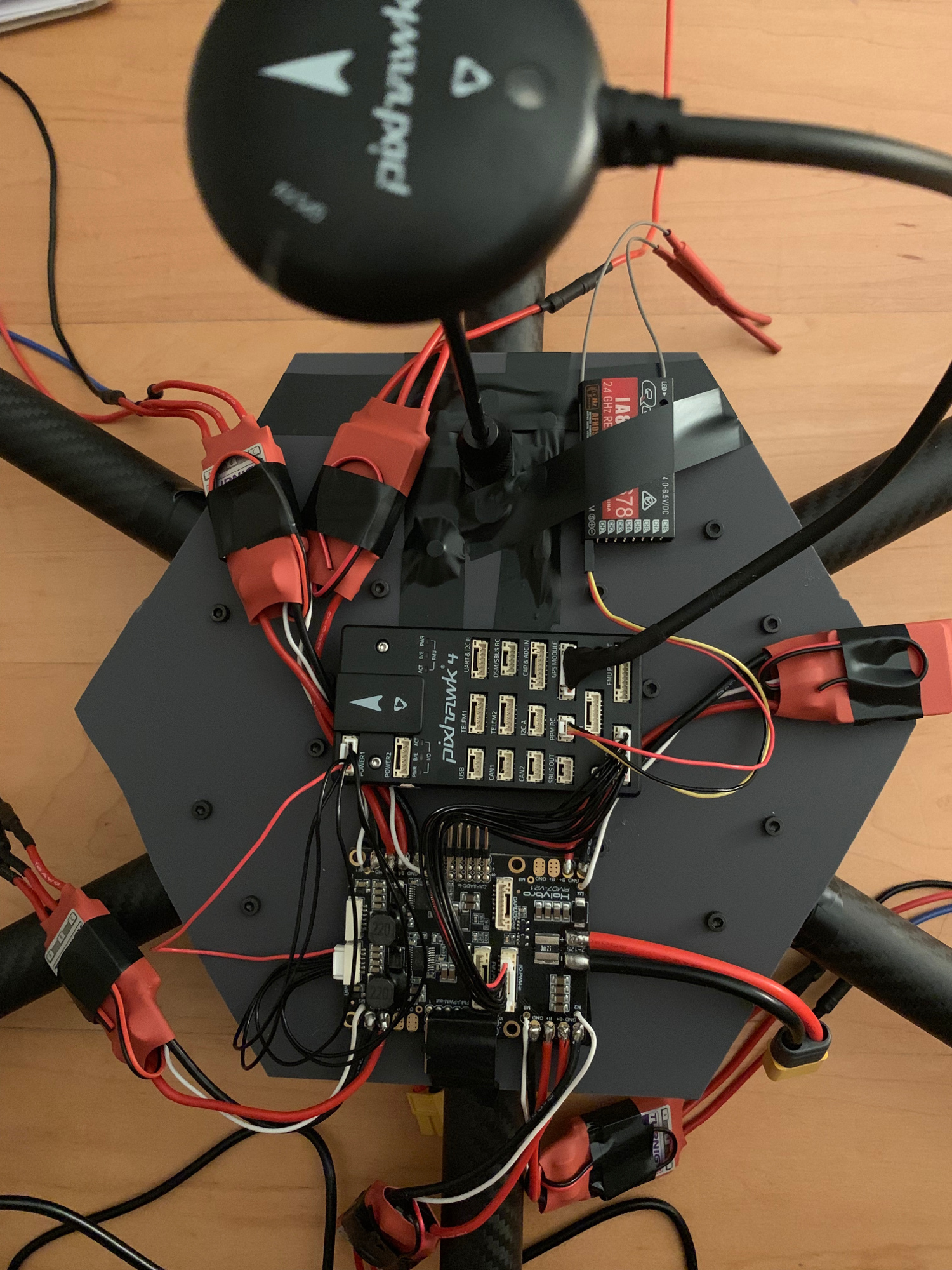
The PWM command ESC use by a cable connected individually on splitter with 8 channels (include in the Holybro package).
The splitter on my Drone is hidden under the Pixhawk close ESC cables.
(See photo with an another splitter for AUX channels)