During flying my Skywalker X8 last year I had a failure of GPS, thankfully while on the ground before the first flight. My current setup has a custom wiring rig as the stock cables are simply not long enough for a big model without compromising the placement of devices. While building the X8 I decided to solder on the pins for the DF13 connectors, which worked great. However after some time the wires tend to break off as there is no strain relief, which of course I first discovered when the GPS failed.
This year I decided I didn’t want to take any chances, I am very particular with redundancy and flight safety and I have yet to have a crash due to component failure. Having a cable break and cause a crash would be a particularly frustrating way to destroy a plane!
The solution I came up with solves two problems, firstly it eliminates the need for having to make up DF13 cables. Secondly it provides a way to run all connections for the Pixhawk to anywhere in the plane using simple IDC cabling and connectors which can be made up easily to suit the application. Also it provides the receptacles for damping balls to help minimise any vibration problems.
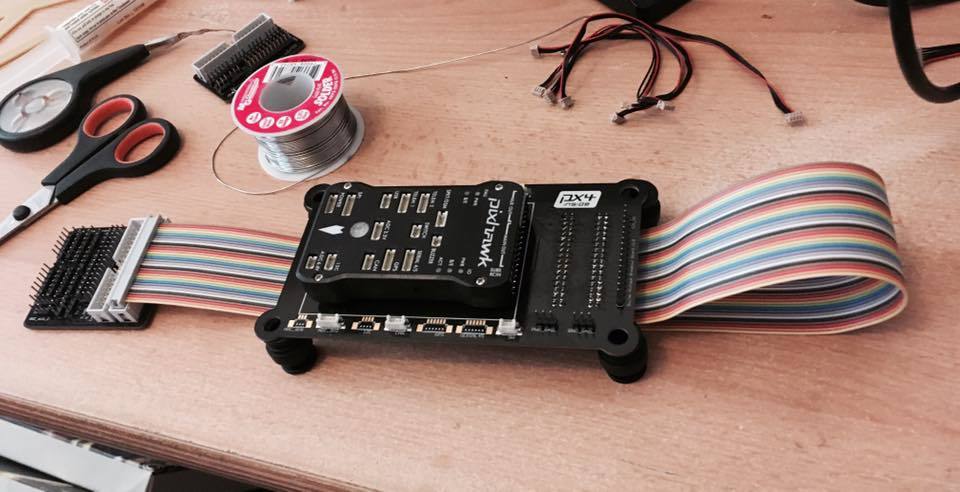
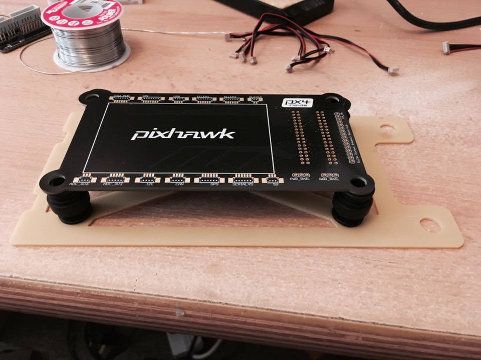
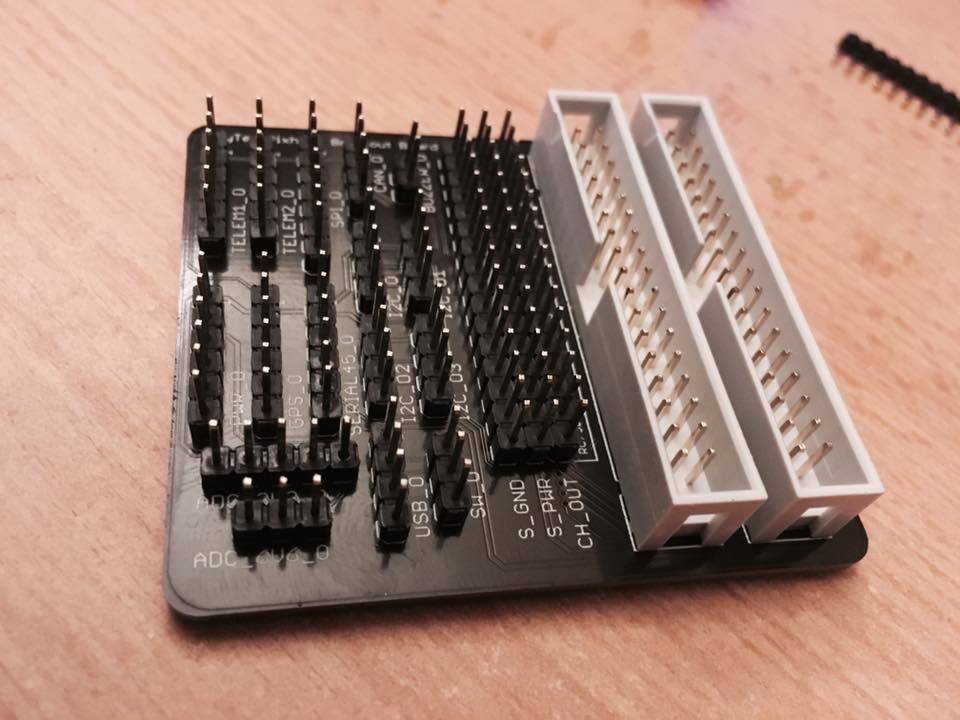
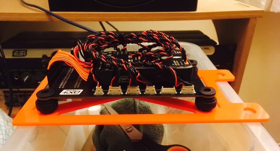
The main carrier PCB features a space in the middle to attach the Pixhawk by normal means of a sticky pad. Around the outside there are sockets for all of the DF13 connections, RC connections and power. Every connection on the PIxhawk connects to the carrier PCB using the (short) standard cables available and standard 0.1" plugs. On the bottom of the board there are two 34 pin IDC connections (standard floppy disk cable) that carry all of the signals to a pair of daughter boards that break out the signals and power using 0.1" headers, which of course are easy to make with a cheap crimper. The plan for the peripherals with DF13 sockets is to make DF13 to 0.1" adapters using standard DF13 cables and cutting them in half, then putting 0.1" connectors on the bare wire end.
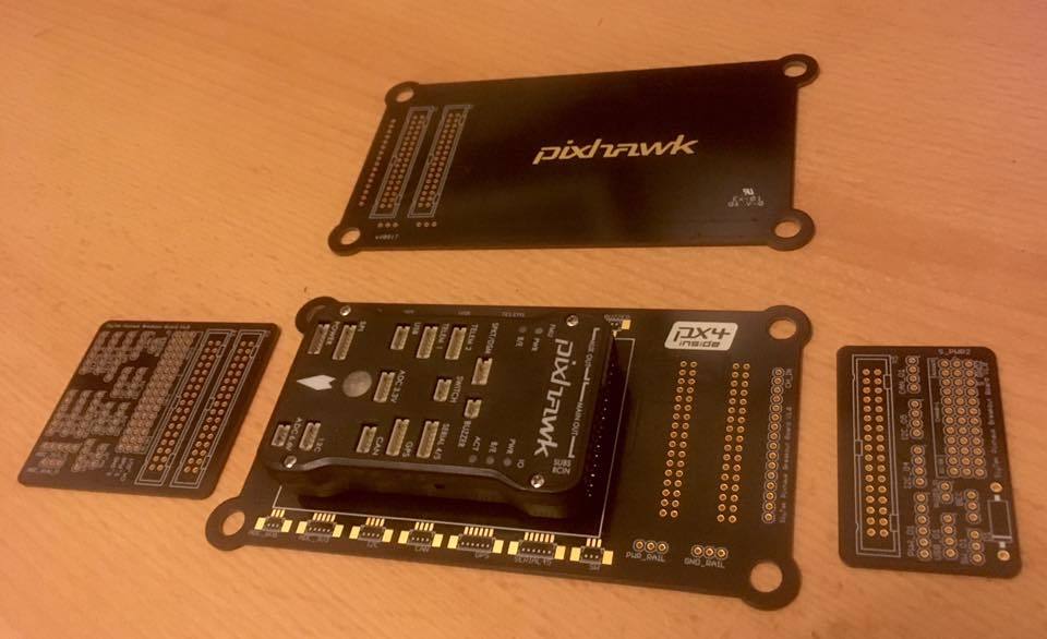
There is a larger daughter board that connects to both ribbon cables and makes all of the signals available. There is also a smaller daughter board that connects to one of the ribbon cables that makes some of the signals available. The idea is the Pixhawk sits in the middle of the plane, the optimum position for the IMU to move around all three axes. The smaller daughter board goes at the back of the plane and gives access to power, I2C, CAN, USB, PWM and the switch, allowing the power electronics and motor to be connected at the back of the plane. I also included a spot for a zener diode to protect the servo rail from over voltage.
The larger daughter board then goes at the front of the plane, keeping the sensitive electronics as far away from the motor as possible. The larger daughter board breaks out all connections allowing for any configuration of instruments and equipment at the front.
This board is of course designed for the X8 and may be of interest to anyone with this airframe, although I’m sure it would work for anyone using a large/long fuselage. I am still assembling the first one and have yet to install it in the plane however I wanted to open a discussion to see if this kind of device would be of interest to the community. The first spin of the PCB was not intended for sale but after recently reading a (very long) thread about DF13 connectors I began to wonder if there was scope to design something that solved these problems that was commercially available. Thanks for reading!
I definitely share your frustration with the DF13 cables, but I’m also wondering if this is a good solution. Now there are many more possible points of failure. Also it’s not just the connector which causes problems, but also the length of the cable. I’m also afraid of interference with your (servo) power wires hugging the data lines.
You also should care about Electromagnetic perturbations with that kind of cables. Plus, avoid 2.56mm headers as you will be able to missplug your components
Thanks for the feedback guys! Great to hear what others have to say.
Yes agreed, however the theory is more points of failure but each with a lesser chance of actually failing when compared with a work-around solution for attaching DF13 connectors (this is just my personal view though, since my soldered DF13s failed, others might have a more robust work-around!) So overall a system less prone to have problems. Thats the theory anyway, we will see if anything actually fails during flight!
Yes cant fault that thought, plus headers are also surprisingly heavy when you start introducing a lot of them! This however isn’t a problem for the X8, its almost 7 foot wing tip to wing tip. For my own solution headers are ideal as I have plenty of spare housings and pins, plus the proper crimp tool. For a more universal design I would defiantly consider something like GH or JST.
I was a little concerned about this but at present all data, power and PWM runs together in a bundle of wires that runs the length of the fuselage. I have been flying it for two years and have never had any crosstalk or interference issues. That said, I have grouped different signal types on the ribbon and separated them with ground lines. I have also kept the traces, in particular the ADC, separated on the board. If I do have problems, I intend on shielding the ribbon.
Do you think there could be problems with a ribbon interfering with the radios?
Yes agreed although this won’t be a problem for my build as I am careful also I fit the connectors the same way round with the small exposed tabs facing the same direction so I don’t need to figure out which way to plug in if I have to disconnect and reconnect something. If I designed a universal one, I would most defiantly use polarised connectors.
Thanks! I made it myself! …although its kind of cheating when you work at a PCB fab we make boards that go in fighter jets, weapons, satellites and other aerospace/military applications, so I have no worries about the reliability of the board. We have also made prototypes for the Parrot AR drone!
This is wonderful. I really like the concept and the execution. I’d love to hear about an available kit if you get to it soon. I’m using a large RVJET airframe with some additional VTOL motors and I wish I had this to work with right now.
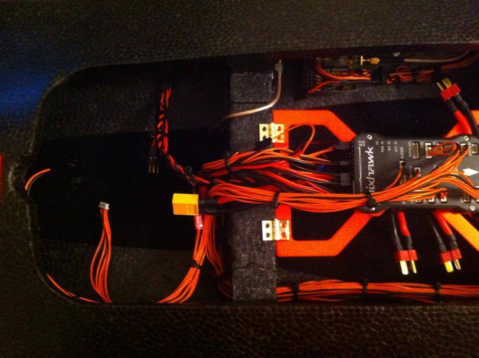
Thanks for the awesome comments! Yes the RVJET looks awesome and is exactly the type of air frame this is designed for. Once I have it installed in the X8 ill post some more pictures, just waiting for some PCB mount DF13 connectors to arrive from RS. In the meantime, here is my existing loom that I am trying to replace, all the signals and power at present run down the loom in the bottom of the picture.
Not sure yet whether ill pursue manufacturing any more of this particular design, however I do have 6 spare PCBs as I needed to fill a manufacturing panel to put round the factory. If a handful of people like yourself wanted one I could put together a few kits using the spare boards, they will only sit in my top draw otherwise!
Out of interest, if kits were available would you be happy to solder the connectors on yourself? Or would you prefer an assembled one? If your pretty familiar with a soldering iron, the DF13 PCB mount connectors are pretty easy to solder and everything else is basic through-hole stuff.
If a handful of people like yourself wanted one I could put together a few kits using the spare boards, they will only sit in my top draw otherwise!
Out of interest, if kits were available would you be happy to solder the connectors on yourself? Or would you prefer an assembled one? If your pretty familiar with a soldering iron, the DF13 PCB mount connectors are pretty easy to solder and everything else is basic through-hole stuff.
Definitely! I’d gladly solder. Crimping… not so much.
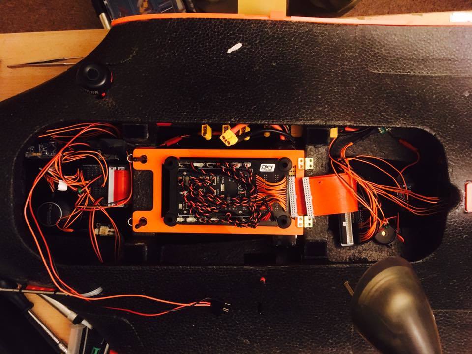
Just thought I would post a little bit of progress with this project! I had been too busy up until recently and as always I’m likely to get my plane ready just in time for the end of summer again!
The initial tests are good! All systems that I have tried so far seem to work fine and there doesn’t seem to be any issues running signals over a long ribbon cable. I had previously used a bundle of wires of the same length with many flights and no trouble (apart from the soldered Harwin connectors breaking) so I was expecting/hoping it to work.
Ill post some pictures of the completed project and some post flight information. For now, things are a bit of a mess still but you can get a good idea